
Mobile Intel Pentium 4 Processor - M and Intel 845MP/MZ Chipset Platform Design Guide

Mobile Intel
®
Pentium
®
4 Processor-M and Intel
®
845MP/845MZ Chipset Platform
106 Design Guide
R
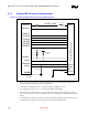
9.3.2. AC’97 Audio Codec Detect Circuit and Configuration Options
The following provides general circuits to implement a number of different Codec configurations. Please
refer to Intel’s White Paper Recommendations for ICHx/AC’97 Audio (Motherboard and
Communication and Network Riser) for Intel’s recommended Codec configurations (available at the
URL given in Section 9.3).
To support more than two channels of audio output, the ICH3-M allows for a configuration where two
audio Codecs work concurrently to provide surround sound capabilities. To maintain data-on-demand
capabilities, the ICH3-M AC’97 controller, when configured for 4 or 6 channels, will wait for all the
appropriate slot request bits to be set before sending data in the SDATA_OUT slots. This allows for
simple FIFO synchronization of the attached Codecs. It is assumed that both Codecs will be programmed
to the same sample rate and that the Codecs have identical (or at least compatible) FIFO depth
requirements. Intel recommends that the Codecs be provided by the same vendor, upon the certification
of their interoperability in an audio channel configuration.
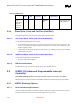
9.3.3. Valid Codec Configurations
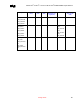
Table 39. Codec Configurations
Valid Codec Configurations
Invalid Codec Configurations
AC(Primary) MC(Primary) + X(any other type of Codec)
MC(Primary) AMC(Primary) + AMC(Secondary)
AMC(Primary) AMC(Primary) + MC(Secondary)
AC(Primary) + MC(Secondary)
AC(Primary) + AC(Secondary)
AC(Primary) + AMC(Secondary)
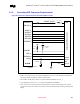
9.3.4. SPKR Pin Consideration
SPKR is used as both the output signal to the system speaker and as a functional strap. The strap function
enables or disables the “TCO Timer Reboot function” based on the state of the SPKR pin on the rising
edge of PWROK. When enabled, the ICH3-M sends an SMI# to the processor upon a TCO timer
timeout. The status of this strap is readable via the NO_REBOOT bit (bit 1, D31: F0, Offset D4h). The
SPKR signal has a weak integrated pull-down resistor (the resistor is only enabled during boot/reset).
Therefore, its default state is a logical zero or set to reboot. To disable the feature, a jumper can be
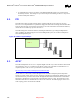
populated to pull the signal line high (see the following figure). The value of the pull-up must be such
that the voltage divider output caused by the pull-up, the effective pull-down (R
eff
), and the ICH3-M’s
integrated pull-down resistor will be read as logic high (0.5 Vcc3_3 to Vcc3_3 + 0.5 V).