
Mobile Intel Pentium 4 Processor - M and Intel 845MP/MZ Chipset Platform Design Guide

Mobile Intel
®
Pentium
®
4 Processor-M and Intel
®
845MP/845MZ Chipset Platform
108 Design Guide
R
• Bypassing and decoupling capacitors should be close to the IC pins, or positioned for the shortest
connections to pins, with wide traces to reduce impedance.
• All resistors in the signal path or on the voltage reference should be metal film. Carbon resistors can
be used for DC voltages and the power supply path, where the voltage coefficient, temperature
coefficient, and noise are not factors.
• Regions between analog signal traces should be filled with copper, which should be electrically
attached to the analog ground plane. Regions between digital signal traces should be filled with
copper, which should be electrically attached to the digital ground plane.
• Locate the crystal or oscillator close to the codec.
Clocking is provided from the primary Codec on the link via BITCLK, and it is derived from a 24.576-
MHz crystal or oscillator. Refer to the primary Codec vendor for the crystal or oscillator requirements.
BITCLK is a 12.288-MHz clock driven by the primary Codec to the digital controller (ICH3-M) and by
any other Codec present. The clock is used as the time base for latching and driving data.
9.3.6. Motherboard Implementation
The following design considerations are provided for the implementation of an ICH3-M platform using
AC’97. These design guidelines have been developed to ensure maximum flexibility for board designers,
while reducing the risk of board-related issues. These recommendations are not the only implementation
or a complete checklist, but they are based on the ICH3-M platform.
• Components such as FET switches, buffers or logic states should not be implemented on the AC-
link signals, except for AC_RST#. Doing so would potentially interfere with timing margins and
signal integrity.
• The ICH3-M supports wake-on-ring from S1-S5 states via the AC’97 link. The Codec asserts
AC_SDIN
n to wake the system. To provide wake capability and/or caller ID, standby power must
be provided to the modem codec. If no Codec is attached to the link, internal pull-downs will
prevent the inputs from floating, so external resistors are not required.
PC_BEEP should be routed through the audio codec. Care should be taken to avoid the introduction of a
pop when powering the mixer up or down.
9.4. USB Guidelines and Recommendations
9.4.1. General Routing and Placement
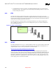
Use the following general routing and placement guidelines when laying out a new design. These
guidelines will help to minimize signal quality and EMI problems. The USB validation efforts focused
on a four-layer motherboard where the first layer is a signal layer, the second plane is power, the third
plane is ground and the fourth is a signal layer. This results in placing most of the routing on the fourth
plane closest to the ground plane, and allowing a higher component density on the first plane. For mobile
motherboards, with different stackup, all USB signals should be ground referenced when using the
appropriate layer for routing.
• Place the ICH3-M and major components on the unrouted board first. With minimum trace lengths,
route high-speed clock, periodic signals and USB differential pairs first. Maintain maximum
possible distance between high-speed clocks/periodic signals to USB differential pairs and any
connector leaving the PCB (i.e. I/O connectors, control and signal headers, or power connectors).