
Mobile Intel Pentium 4 Processor - M and Intel 845MP/MZ Chipset Platform Design Guide

Mobile Intel
®
Pentium
®
4 Processor-M and Intel
®
845MP/845MZ Chipset Platform
110 Design Guide
R
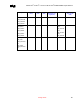
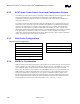
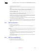
Table 40. USB Signals
Signal Width
(mils)
Space
(mils)
Mismatch
length (mils)
Relative
To
Space with other
signals (mils)
Notes
USB Signals
Group
USB_PN0 to
USB_PN5
USB_PP0 to
USB_PP5
4 6 ± 75 Signal
differential
pair
20 Clock and PCI should
be 50 mils away from
USB signals (min)
9.4.4. Plane Splits, Voids and Cut-Outs (Anti-Etch)
The following guidelines apply to the use of plane splits voids and cutouts.
9.4.4.1. VCC Plane Splits, Voids, and Cut-Outs (Anti-Etch)
Use the following guidelines for the VCC plane.
• Traces should not cross anti-etch, for it greatly increases the return path for those signal traces. This
can be true of USB signals, high-speed clocks, and signal traces as well as slower signal traces that
might be coupling to them.
• Avoid routing of USB signals 50-mil of any anti-etch to avoid coupling to the next split or radiating
from the edge of the PCB.
9.4.4.2. GND Plane Splits, Voids, and Cut-Outs (Anti-Etch)
Use the following guideline for the GND plane.
• Avoid anti-etch on the GND plane.
9.4.4.3. EMI Recommendation
Recommended a 45-pF capacitor for each data line for its USB EMI solution.
9.5. IOAPIC (I/O Advanced Programmable Interrupt
Controller)
Intel 845MP/845MZ platform does not support IOAPIC when C2/C3/C4 states are enabled.
Mobile Systems not using the IOAPIC should disable IOAPIC functionality through the system BIOS.
9.5.1. IOAPIC Disabling Options
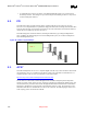
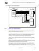
9.5.1.1. Recommended Implementation
Intel recommends that IOAPIC be disabled in software while the connections to the board are as shown
in Figure 52. Software can be used to turn off PICCLK from clock generator.