
Mobile Intel Pentium 4 Processor - M and Intel 845MP/MZ Chipset Platform Design Guide

Mobile Intel
®
Pentium
®
4 Processor-M and Intel
®
845MP/845MZ Chipset Platform
112 Design Guide
R
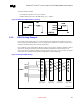
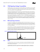
Figure 53 is an example. It is up to the board designer to route these signals in a way that will prove the
most efficient for their particular system. A PCI slot can be routed to share interrupts with any of the
ICH3-M’s internal device/functions (but at a higher latency cost).
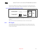
9.6. SMBus 2.0/SMLink Interface
The SMBus interface on the ICH3-M is the same as that on the ICH2-M. It uses two signals SMBCLK
and SMBDATA to send and receive data from components residing on the bus. These signals are used
exclusively by the SMBus Host Controller. The SMBus Host Controller resides inside the ICH3-M. If
the SMBus is used only for the RAMBUS SPD EEPROMs (one on each RIMM*), both signals should
be pulled up with a 4.7-k
Ω resistor to 3.3 V.
The ICH3-M incorporates a SMLink interface supporting AOL*, AOL2* and a slave functionality. It
uses two signals SMLINK[1:0]. SMLINK[0] corresponds to an SMBus clock signal and SMLINK[1]
corresponds to an SMBus data signal. These signals are part of the SMB Slave Interface.
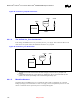
For Alert on LAN* (AOL*) functionality, the ICH3-M transmits heartbeat and event messages over the
interface. When using the 82562EM Platform LAN Connect Component, the ICH3-M’s integrated LAN
Controller will claim the SMLink heartbeat and event messages and send them out over the network. An
external, AOL2*-enabled LAN Controller (i.e. Gamla) will connect to the SMLink signals to receive
heartbeat and event messages, as well as access the ICH3-M SMBus Slave Interface. The slave interface
function allows an external microcontroller to perform various functions. For example, the slave write
interface can reset or wake a system, generate SMI# or interrupts, and send a message. The slave read
interface can read the system power state, read the watchdog timer status, and read system status bits.
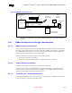
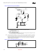
Both the SMBus Host Controller and the SMBus Slave Interface obey the SMBus 1.0 protocol, so the
two interfaces can be externally wire-OR’d together to allow an external management ASIC (such as
Gamla) to access targets on the SMBus as well as the ICH3-M Slave interface. Additionally, the ICH3-M
supports slave functionality, including the Host Notify protocol, on the SMLink pins. Therefore, in order
to be fully compliant with the SMBus 2.0 specification (which requires the Host Notify cycle), the
SMLink and SMBus signals
must be tied together externally. This is done by connecting SMLink[0] to
SMBCLK and SMLink[1] to SMBDATA.