
Mobile Intel Pentium 4 Processor - M and Intel 845MP/MZ Chipset Platform Design Guide

Mobile Intel
®
Pentium
®
4 Processor-M and Intel
®
845MP/845MZ Chipset Platform
118 Design Guide
R
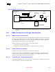
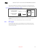
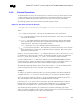
Figure 60. External Circuitry for the ICH3-M RTC
1KΩ
1uF
15KΩ
1uF
+V3ALWAYS +V_RTC
1KΩ
1KΩ
0.047uF
10MΩ
10pF
10pF
32.768KHz
10MΩ
RTC_X2
RTC_X1
RTC_VBIAS
RTC_RST#
BATT_SKT
NOTES:
1. The exact capacitor value needs to be based on what the crystal maker recommends.
(Typical values for C2 and C3 are 18 pF.)
2. V
CCRTC
: Power for RTC Well.
3. RTCX2: Feedback for the external crystal.
4. RTCX1: Input to the internal oscillator.
5. V
BIAS
: RTC BIAS Voltage – This ball is used to provide a reference voltage, and this DC voltage sets a current,
which is mirrored throughout the oscillator and buffer circuitry.
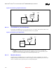
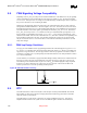
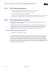
Note: Even if the ICH3-M internal RTC is not used, it is still necessary to supply clock inputs to X1 and X2 of
the ICH3-M because other signals are gated off that clock in suspend modes. However, in this case, the
frequency (32.768 kHz) of the clock inputs is not critical; a lower-cost crystal can be used or a single
clock input can be driven into X1 with X2 left as no connect; Figure 61 illustrates this.
This is not a
validated configuration with ICH3-M.
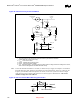
Figure 61. RTC Connections When Not Using Internal RTC
Internal
External
X1 X2
5M
32 KHz
No Connection