
Mobile Intel Pentium 4 Processor - M and Intel 845MP/MZ Chipset Platform Design Guide

Mobile Intel
®
Pentium
®
4 Processor-M and Intel
®
845MP/845MZ Chipset Platform
Design Guide 119
R
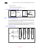
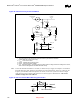
9.9.2. External Capacitors
To maintain the RTC accuracy, the external capacitor C3 needs to be 0.047 µF, and the capacitor values
C1 and C2 should be chosen to provide the manufacturer’s specified load capacitance (Cload) for the
crystal when combined with the parasitic capacitance of the trace, socket (if used), and package.
The following equation can be used to choose the external capacitance values:
Equation 2. RTC External Capacitor Equation
C
load
= [(C
1
+ C
in1
+ C
trace1
)*(C
2
+ C
in2
+ C
trace2
) ]/[ (C
1
+ C
in1
+ C
trace1
+ C
2
+ C
in2
+ C
trace2
)] + C
parasitic
Where:
C
load
= Crystal’s load capacitance. This value can be obtained from crystal’s specification.
C
in1
, C
in2
= input capacitances at RTCX1, RTCX2 balls of the ICH3-M. These values can be obtained
in the ICH3-M’s datasheet.
C
trace1
, C
trace2
= Trace length capacitances measured from crystal terminals to RTCX1, RTCX2 balls.
These values depend on the characteristics of board material, the width of signal traces and the
length of the traces. Typical value is approximately equal to:
C
trace
= trace length * 2 pF / inch (dependent upon board characteristics)
C
parasitic
= Crystal’s parasitic capacitance. This capacitance is created by the existence of two electrode
plates and the dielectric constant of the crystal blank inside the crystal part. Refer to the crystal’s
specification to obtain this value.
Ideally, C
1,
C
2
can be chosen such that C
1
= C
2
. Using the equation of C
load
above, the value of C
1,
C
2
can
be calculated to give the best accuracy (closest to 32.768 kHz) of the RTC circuit at room temperature.
However, C
2
can be chosen such that C
2
> C
1
. Then C
1
can be trimmed to obtain 32.768 kHz.
In certain conditions, both C
1
, C
2
values can be shifted away from the theoretical values (calculated
values from the above equation) to obtain the closest oscillation frequency to 32.768 kHz. When C
1,
C
2
value are smaller then the theoretical values, the RTC oscillation frequency will be higher.
The following example will illustrates the use of the practical values C
1
, C
2
in the case that theoretical
values can not guarantee the accuracy of the RTC in low temperature condition:
Example 1:
According to a required 12-pF load capacitance of a typical crystal that is used with the ICH3-M, the
calculated values of C
1
= C
2
is 10 pF at room temperature (25
0
C) to yield a 32.768-kHz oscillation.
At 0
0
C the frequency stability of crystal gives –23 ppm (assumed that the circuit has 0 ppm at 25
0
C).
This makes the RTC circuit oscillate at 32.767246 kHz instead of 32.768 kHz.
If the values of C
1
, C
2
are chosen to be 6.8 pF instead of 10 pF. This will make the RTC oscillate at
higher frequency at room temperature (+23 ppm) but this configuration of C
1
/ C
2
makes the circuit
oscillate closer to 32.768 kHz at 0
°
C. The 6.8-pF value of C1 and C2 is the practical value.
Note that the temperature dependency of crystal frequency is parabolic relationship (ppm / degree
square). The effect of changing crystal’s frequency when operating at 0
°
C (25
°
below room temperature)
is the same when operating at 50
°
C (25
°
C above room temperature).