
Mobile Intel Pentium 4 Processor - M and Intel 845MP/MZ Chipset Platform Design Guide

Mobile Intel
®
Pentium
®
4 Processor-M and Intel
®
845MP/845MZ Chipset Platform
120 Design Guide
R
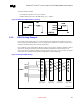
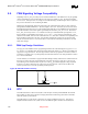
9.9.3. RTC Layout Considerations
• Keep the RTC lead lengths as short as possible; around ¼ inch is sufficient.
• Minimize the capacitance between Xin and Xout in the routing.
• Put a ground plane under the XTAL components.
• Don’t route switching signals under the external components (unless on the other side of the board).
• The oscillator Vcc should be clean; use a filter, such as an RC lowpass, or a ferrite inductor.
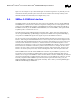
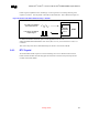
9.9.4. RTC External Battery Connection
The RTC requires an external battery connection to maintain its functionality and its RAM while the
ICH3-M is not powered by the system.
Example batteries are: Duracell* 2032, 2025, or 2016 (or equivalent), which can give many years of
operation. Batteries are rated by storage capacity. The battery life can be calculated by dividing the
capacity by the average current required. For example, if the battery storage capacity is 170 mAh
(assumed usable) and the average current required is 3 µA, the battery life will be at least:
Equation 3. RTC External Battery Life Equation
170,000 uAh / 3 uA = 56,666 h = 6.4 years
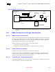
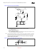
The voltage of the battery can affect the RTC accuracy. In general, when the battery voltage decays, the
RTC accuracy also decreases. . The battery voltage of the RTC must be greater than 2V at all time to
ensure the accuracy of the RTC clock. The battery must be connected to the ICH3-M via an isolation
Schottky diode circuit. The Schottky diode circuit allows the ICH3-M RTC-well to be powered by the
battery when the system power is not available, but by the system power when it is available. To do this,
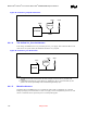
the diodes are set to be reverse biased when the system power is not available. The following figure is an
example of a diode circuit that is used.