
Mobile Intel Pentium 4 Processor - M and Intel 845MP/MZ Chipset Platform Design Guide

Mobile Intel
®
Pentium
®
4 Processor-M and Intel
®
845MP/845MZ Chipset Platform
Design Guide 121
R
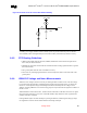
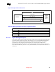
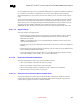
Figure 62. A Diode Circuit to Connect RTC External Battery
VCC3_3SBY
VccRTC
1.0uF
1K
A standby power supply should be used in a mobile system to provide continuous power to the RTC
when available, which will significantly increase the RTC battery life and thereby the RTC accuracy.
9.9.5. RTC Routing Guidelines
• All RTC OSC signals (RTCX1, RTCX2, VBIAS) should all be routed with trace lengths of less
than 1 inch, the shorter the better.
• Minimize the capacitance between RTCX1 and RTCX2 in the routing (optimal would be a ground
line between them).
• Put a ground plane under all of the external RTC circuitry.
• Don’t route any switching signals under the external components (unless on the other side of the
ground plane).
9.9.6. VBIAS DC Voltage and Noise Measurements
VBIAS is a DC voltage level that is necessary for biasing the RTC oscillator circuit. This DC voltage
level is filtered out from the RTC oscillation signal by the RC Network of R2 and C3 (see Figure 60)
therefore it is self-adjusted voltage. Board designers should not manually bias the voltage level on
VBIAS. Checking VBIAS level is used for testing purposes only to determine the right bias condition of
the RTC circuit.
VBIAS should be at least 200-mV DC. The RC network of R2 and C3 will filter out most of AC signal
that exist on this ball, however, the noise on this ball should be kept minimal in order to guarantee the
stability of the RTC oscillation.
Probing VBIAS requires the same technique as probing the RTCX1, RTCX2 signals (using Op-Amp).
See Application Note AP-728 for further details on measuring techniques.