
Mobile Intel Pentium 4 Processor - M and Intel 845MP/MZ Chipset Platform Design Guide

Mobile Intel
®
Pentium
®
4 Processor-M and Intel
®
845MP/845MZ Chipset Platform
Design Guide 127
R
Note: Some suggestions are specific to a 4.5-mil stackup.
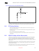
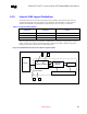
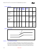
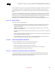
• Maximum mismatch between the length of the clock trace and the length of any data trace is 0.5
inches (clock trace must be longest). See Table 44 below for summary of recommendations
• Maintain constant symmetry and spacing between the traces within a differential pair.
• Keep the signal trace lengths of a differential pair equal to each other.
• Keep the total length of each differential pair under 4 inches. [Many customer designs with
differential traces longer than 5 inches have had one or more of the following issues: IEEE phy
conformance failures, excessive EMI, and/or degraded receive BER.]
• Do not route the transmit differential traces closer than 100 mils to the receive differential traces.
• Do not route any other signal traces both parallel to the differential traces, and closer than 100 mils
to the differential traces (300 mils is recommended).
• Keep maximum separation between differential pairs to 7 mils.
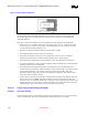
• For high-speed signals, the number of corners and vias should be kept to a minimum. If a 90° bend
is required, Intel recommends using two 45° bends instead.
• Traces should be routed away from board edges by a distance greater than the trace height above the
ground plane. This allows the field around the trace to couple more easily to the ground plane rather
than to adjacent wires or boards.
• Do not route traces and vias under crystals or oscillators. This will prevent coupling to or from the
clock. And as a general rule, place traces from clocks and drives at a minimum distance from
apertures by a distance that is greater than the largest aperture dimension.