
Mobile Intel Pentium 4 Processor - M and Intel 845MP/MZ Chipset Platform Design Guide

Mobile Intel
®
Pentium
®
4 Processor-M and Intel
®
845MP/845MZ Chipset Platform
128 Design Guide
R
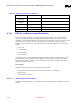
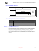
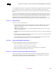
Table 44. LAN Signals
Signal Max
length
(inch)
Widt
h
(mils)
Space
btwn
diff
pair
(mils)
Space btwn
trans. recv.
diff pair or
other
signals(mils
)
Mismatc
h relative
max.
(mils)
Relative
To
Notes
Signals Group#lan1
LAN_RXD0 to
LAN_RXD2 LAN_TXD0
to LAN_TXD2
LAN_RST
10 (min
3.5)
4 *4 8 -500 LAN_JCLK
Diff. Pair
must be
the same
length (±10
mils)
Signals Group#lan2
TDP (pin9, J23A)
TDN (pin10, J23A)
LAN_RDP
LAN_RDN
LAN_JCL
4 4 7 100 +/-10 Signals
Group#lan2
diff pair
Diff. Pair
must be
the same
length (±10
mils)
LAN_JCLK 10 (min
3.5)
4 none 16 +500 Signals
Group#lan1
LAN_JCLK
is equal to
Signals
Group#lan
1 or longer
by 500 mil
(max)
NOTE: *This parameter is not for diff pairs, it is the space between datalines.
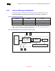
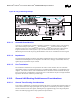
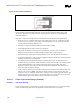
Figure 66. Trace Routing
45
Trace Routing
9.10.2.1.1. Trace Geometry and Length
The key factors in controlling trace EMI radiation are the trace length and the ratio of trace-width to
trace-height above the ground plane. To minimize trace inductance, high-speed signals and signal layers
that are close to a ground or power plane should be as short and wide as practical. Ideally, this trace
width to height above the ground plane ratio is between 1:1 and 3:1. To maintain trace impedance, the
width of the trace should be modified when changing from one board layer to another if the two layers