
Mobile Intel Pentium 4 Processor - M and Intel 845MP/MZ Chipset Platform Design Guide

Mobile Intel
®
Pentium
®
4 Processor-M and Intel
®
845MP/845MZ Chipset Platform
Design Guide 129
R
are not equidistant from the power or ground plane. Differential trace impedances should be controlled to
be ~100 ohms. It is necessary to compensate for trace-to-trace edge coupling, which can lower the
differential impedance by up to 10 ohms, when the traces within a pair are closer than 30 mils (edge to
edge).
Traces between decoupling and I/O filter capacitors should be as short and wide as practical. Long and
thin traces are more inductive and would reduce the intended effect of decoupling capacitors. Also for
similar reasons, traces to I/O signals and signal terminations should be as short as possible. Vias to the
decoupling capacitors should be sufficiently large in diameter to decrease series inductance.
Additionally, the PLC should not be closer than one inch to the connector/magnetic/edge of the board.
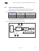
9.10.2.1.2. Signal Isolation
Some rules to follow for signal isolation:
• Separate and group signals by function on separate layers if possible. Maintain a gap of 100 mils
between all differential pairs (Phone line and Ethernet) and other nets, but group associated
differential pairs together.
NOTE: Over the length of the trace run, each differential pair should be at least 0.3 inches away
from any parallel signal traces.
• Physically group together all components associated with one clock trace to reduce trace length and
radiation.
• Isolate I/O signals from high speed signals to minimize cross talk, which can increase EMI emission
and susceptibility to EMI from other signals.
• Avoid routing high-speed LAN or Phone line traces near other high-frequency signals associated
with a video controller, cache controller, CPU, or other similar devices.
9.10.2.2. Power and Ground Connections
Some rules and guidelines to follow for power and ground connections:
• All Vcc pins should be connected to the same power supply.
• All Vss pins should be connected to the same ground plane.
• Four to six decoupling capacitors, including two 4.7-µF capacitors are recommended
• Place decoupling as close as possible to power pins.
9.10.2.2.1. General Power and Ground Plane Considerations
To properly implement the common mode choke functionality of the magnetic module the chassis or
output ground (secondary side of transformer) should be separated from the digital or input ground
(primary side) by a physical separation of 100 mils minimum.