
Mobile Intel Pentium 4 Processor - M and Intel 845MP/MZ Chipset Platform Design Guide

Mobile Intel
®
Pentium
®
4 Processor-M and Intel
®
845MP/845MZ Chipset Platform
Design Guide 131
R
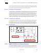
9.10.2.3.2. Ground Plane
A layout split (100 mils) of the ground plane under the magnetic module between the primary and
secondary side of the module is recommended. It is also recommended to minimize the digital noise
injected into the 82562 common ground plane. Suggestions include optimizing decoupling on
neighboring noisy digital components, isolating the 82562 digital ground using a ground cutout, etc.
9.10.2.3.3. Power Plane
Physically separate digital and analog power planes must be provided to prevent digital switching noise
from being coupled into the analog power supply planes VDD_A. Analog power may be a metal fill
“island”, separated from digital power, RC filtered from the digital power.
9.10.2.3.4. Bottom Layer Routing
The digital high-speed signals that include all of the LAN interconnect interface signals are routed on the
bottom layer.
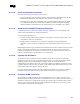
9.10.2.4. Common Physical Layout Issues
Here is a list of common physical layer design and layout mistakes in LAN On Motherboard Designs.
• Unequal length of the two traces within a differential pair. Inequalities create common-mode noise
and will distort the transmit or receive waveforms.
• Lack of symmetry between the two traces within a differential pair. [Each component and/or via that
one trace encounters, the other trace must encounter the same component or a via at the same
distance from the PLC.] Asymmetry can create common-mode noise and distort the waveforms.
• Excessive distance between the PLC and the magnetic or between the magnetic and the RJ-45/11
connector. Beyond a total distance of about 4 inches, it can become extremely difficult to design a
spec-compliant LAN product. Long traces on FR4 (fiberglass epoxy substrate) will attenuate the
analog signals. Also, any impedance mismatch in the traces will be aggravated if they are longer
(see #9 below). The magnetic should be as close to the connector as possible (less than or equal to
one inch).
• Routing any other trace parallel to and close to one of the differential traces. Crosstalk getting onto
the receive channel will cause degraded long cable BER. Crosstalk getting onto the transmit channel
can cause excessive emissions (failing FCC) and can cause poor transmit BER on long cables. At a
minimum, other signals should be kept 0.3 inches from the differential traces.
• Routing the transmit differential traces next to the receive differential traces. The transmit trace that
is closest to one of the receive traces will put more crosstalk onto the closest receive trace and can
greatly degrade the receiver's BER over long cables. After exiting the PLC, the transmit traces
should be kept 0.3 inches or more away from the nearest receive trace. The only possible exceptions
are in the vicinities where the traces enter or exit the magnetic, the RJ-45/11, and the PLC.
• Use of an inferior magnetic module. The magnetic modules that we use have been fully tested for
IEEE PLC conformance, long cable BER, and for emissions and immunity. (Inferior magnetic
modules often have less common-mode rejection and/or no auto transformer in the transmit
channel.)