
Mobile Intel Pentium 4 Processor - M and Intel 845MP/MZ Chipset Platform Design Guide

Mobile Intel
®
Pentium
®
4 Processor-M and Intel
®
845MP/845MZ Chipset Platform
Design Guide 135
R
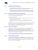
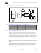
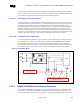
Figure 69. Critical Dimensions for Component Placement
Gilad
A
B
ICH3-M
EEPROM
Phone
RJ11
Magnetics
Module
LPF
Line
RJ11
C
Table 45. 82562EH Home/PNA* Critical Dimensions for Component Placement
Distance Priority Guideline
B 1 < 1 inch
A 2 < 1 inch
C 3 < 1 inch
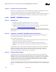
9.10.3.6.1. Distance from Magnetic Module to Line RJ11
This distance ‘B’ should be given highest priority and should be less then 1 inch. In regards to trace
symmetry, route differential pairs with consistent separation and with exactly the same lengths and
physical dimensions.
Asymmetrical and unequal length in the differential pairs contribute to common mode noise and this can
degrade the receive circuit performance and contribute to radiated emissions from the transmit side.
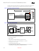
9.10.3.6.2. Distance from 82562EH to Magnetic Module
Due to the high-speed of signals present, distance ‘A’ between the 82562EH and the magnetic should
also be less than 1 inch, but should be second priority relative to distance form connects to the magnetic
module.
And in general, any section of trace that is intended for use with high-speed signals should observe
proper termination practices. Proper signal termination can reduce reflections caused by impedance
mismatches between device and traces route. The reflections of a signal may have a high-frequency
component that may contribute more EMI than the original signal itself.