
Mobile Intel Pentium 4 Processor - M and Intel 845MP/MZ Chipset Platform Design Guide

Mobile Intel
®
Pentium
®
4 Processor-M and Intel
®
845MP/845MZ Chipset Platform
136 Design Guide
R
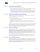
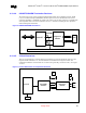
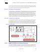
9.10.3.6.3. Distance from LPF to Phone RJ11
This distance ‘C’ should be less then 1 inch. In regards to trace symmetry, route differential pairs with
consistent separation and with exactly the same lengths and physical dimensions.
Asymmetrical and unequal length in the differential pairs contribute to common mode noise and this can
degrade the receive circuit performance and contribute to radiated emissions from the transmit side.
9.10.4. 82562ET / 82562EM Guidelines
9.10.4.1. Related Docs
• 82562ET LAN on Motherboard Design Guide (AP-414): OR-2336
• 82562ET/EM PCB Design Platform LAN Connect (AP-412): OR-2059
• 82562ET 10/100 Mbps Platform LAN Connect (PLC) Product Datasheet (Order# A00358-004),
available at http://www-niooem.jf.intel.com/components.htm
and on IBL
For correct LAN performance, designers must follow the general guidelines outlined in Section 9.10.2.
Additional guidelines for implementing an 82562ET or 82562EM Platform LAN Connect component are
provided below.
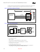
9.10.4.2. Guidelines for 82562ET / 82562EM Component Placement
Component placement can affect signal quality, emissions, and temperature of a board design. This
section will provide guidelines for component placement.
Careful component placement can:
• Decrease potential problems directly related to electromagnetic interference (EMI), which could
cause failure to meet FCC and IEEE test specifications.
• Simplify the task of routing traces. To some extent, component orientation will affect the
complexity of trace routing. The overall objective is to minimize turns and crossovers between
traces.
Minimizing the amount of space needed for the Ethernet LAN interface is important because all other
interface will compete for physical space on a motherboard near the connector edge. As with most
subsystems, the Ethernet LAN circuits need to be as close as possible to the connector. Thus, it is
imperative that all designs be optimized to fit in a very small space.
9.10.4.3. Crystals and Oscillators
To minimize the effects of EMI, clock sources should not be placed near I/O ports or board edges.
Radiation from these devices may be coupled onto the I/O ports or out of the system chassis. Crystals
should also be kept away from the Ethernet magnetic module to prevent interference of communication.
The retaining straps of the crystal (if they should exist) should be grounded to prevent possibility
radiation from the crystal case and the crystal should lay flat against the PC board to provide better
coupling of the electromagnetic fields to the board.
For a noise free and stable operation, place the crystal and associated discrete as close as possible to the
82562ET or 82562EM, keeping the trace length as short as possible and do not route any noisy signals in
this area.