
Mobile Intel Pentium 4 Processor - M and Intel 845MP/MZ Chipset Platform Design Guide

Mobile Intel
®
Pentium
®
4 Processor-M and Intel
®
845MP/845MZ Chipset Platform
Design Guide 139
R
The most sensitive signal returns closest to the chassis ground should be connected together. This will
result in a smaller loop area and reduce the likelihood of crosstalk. The effect of different configurations
on the amount of crosstalk can be studied using electronics modeling software.
9.10.4.6.1. Terminating Unused Connections
In Ethernet designs it is common practice to terminate unused connections on the RJ-45 connector and
the magnetic module to ground. Depending on overall shielding and grounding design, this may be done
to the chassis ground, signal ground, or a termination plane. Care must be taken when using various
grounding methods to insure that emission requirements are met. The method most often implemented is
called the “Bob Smith” Termination. In this method a floating termination plane is cut out of a power
plane layer. This floating plane acts as a plate of a capacitor with an adjacent ground plane and couples
capacitively to the ground plane creating the required 1500 pF of capacitance. The signals can be routed
through 75-
Ω resistors to the plane. Stray energy on unused balls is then carried to the plane.
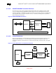
9.10.4.6.2. Termination Plane Capacitance
It is recommended that the termination plane capacitance equal a minimum value of 1500 pF. This helps
reduce the amount of crosstalk on the differential pairs (TDP/TDN and RDP/RDN) from the unused
pairs of the RJ45. Pads may be placed for an additional capacitance to chassis ground, which may be
required if the termplane capacitance is not large enough to pass EFT (Electrical Fast Transient) testing.
If a discrete capacitor is used, to meet the EFT requirements it should be rated for at least 1000 Vac.
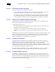
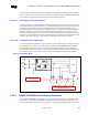
Figure 72. Termination Plane
N/C
RJ-45
Magnetics Module
RDP
RDN
TDP
TDN
Termination Plane
Addition Capacitance that may need to be
added for EFT testing
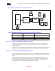
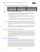
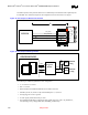
9.10.5. 82562ET/82562EH Dual Footprint Guidelines
These guidelines characterize the proper layout for a dual footprint solution. This configuration enables
the developer to install either the 82562EH or the 82562ET/82562EM components while having only
one motherboard design. The following are guidelines for the 82562ET/82562EH Dual Footprint option.