
Mobile Intel Pentium 4 Processor - M and Intel 845MP/MZ Chipset Platform Design Guide


Mobile Intel
®
Pentium
®
4 Processor-M and Intel
®
845MP/845MZ Chipset Platform
Design Guide 149
R
• Mult0 pin (pin #43) connected to HIGH – making the multiplication factor as 6.
• Iref pin (pin # 42) is connected to ground through a 475-Ohm (± 1 % tol.) resistor – making the Iref
as 2.32 mA.
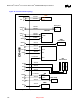
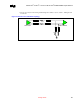
Figure 79. Source Shunt Termination Topology
L1
L1' L2'
L2
L4'
L4
L3'
L3
Clock Driver
CPU or MCH-M
RTRT
RS
RS
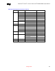
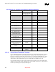
Table 50. Source Shunt Termination Topology BCLK [1:0]# Routing Guidelines
Layout Guideline Value Illustration Notes
BCLK Skew between agents 400 ps totalBudget:150 ps
for Clock driver250 ps for
interconnect
1, 2, 3, 4
Differential pair spacing S max. Figure 80 5, 6
Spacing to other traces 4 S- 5 S mils Figure 80 --
Line width 4.0 mils Figure 80 7
Systemboard Impedance –
Differential
100Ω ± 15% -- 8
Systemboard Impedance – odd mode 55 Ω ± 15% -- 9
Processor routing length – L1, L1':
Clock driver to Rs
0.5” max Figure 79
13
Processor routing length – L2, L2' 0 – 0.2" Figure 79 13
Processor routing length – L3, L3’:
RS-RT node to Rt
0 - 0.5" Figure 79 13
Processor routing length – L4, L4':
RS-RT Node to Load
2 – 8" Figure 79
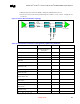
MCH-M routing length – L1, L1’: Clock
Driver to RS
0.5” max Figure 79 13
MCH-M routing length – L2, L2' 0 – 0.2" Figure 79 13
MCH-M routing length – L3, L3’: RS-
RT node to Rt
0 – 0.2" Figure 79 13
MCH-M routing length – L4, L4': RS-
RT Node to Load
2 – 8" Figure 79
Clock driver to Processor and clock
di t Chi tl th
thi
+260 mils Figure 79 10