
Mobile Intel Pentium 4 Processor - M and Intel 845MP/MZ Chipset Platform Design Guide

Mobile Intel
®
Pentium
®
4 Processor-M and Intel
®
845MP/845MZ Chipset Platform
Design Guide 157
R
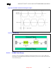
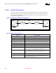
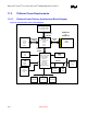
Figure 88. Topology for PCICLK to PCI Slot
A
R1
Clock
Driver
PCI Device
B C
PCI
Connector
Trace on PCI
Card
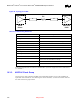
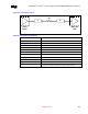
Table 56. PCICLK Routing Guidelines
Parameter Routing Guidelines
Clock Group PCICLK
Topology Point to point
Reference Plane Ground Referenced (Contiguous over entire Length)
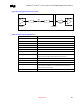
Characteristic Trace Impedance (Zo) 50 Ohms ± 15%
Trace Width 5 mils
Trace Spacing 10 mils
Spacing to other traces 10 mils
Trace Length – A Same as CLK33 Trace A
This trace must be exactly length matched to CLK33 Trace A
Trace Length – B (Routed equal to CLK33 Trace B) – 2.5”
Trace Length – C Routed 2.50” per the PCI Specification
Resistor R1 = 33 Ohms ± 1%
Skew Requirements Should have a maximum of ±1 ns skew between the clocks within this
group, and also a maximum of
±1 ns skew between the clocks of this
group and that of group CLK33.
Maximum via Count per signal 1