
Mobile Intel Pentium 4 Processor - M and Intel 845MP/MZ Chipset Platform Design Guide


Mobile Intel
®
Pentium
®
4 Processor-M and Intel
®
845MP/845MZ Chipset Platform
162 Design Guide
R
Signal Names Voltage
(V)
Current
(A)*
Tolerance Enable Description
+ 9% AC
PLL and VID circuitry.
11.3.3. Power Supply Control Signals
11.3.3.1. SLP_S3#
SLP_S3# is a signal coming from the ICH3-M. Deassertion of SLP_S3# enables the outputs for the
following rails: +V1.25, +V1_5S, +V1_8S, +V3_3S, +V5S, and +V12S. SLP_S3# will be asserted
when the system enters S3/S4/S5 or powers off. SLP_S3# is deasserted when the system boots up or
exits from S3, S4, and S5.
11.3.3.2. SLP_S5#
SLP_S5# is a signal coming from the ICH3-M. Deassertion of SLP_S5# enables the outputs for the
following rails: +V1_8, +V2_5, +V3_3, and +V5. SLP_S5# will be asserted when the system enters
S4/S5 or powers off. SLP_S5# is deasserted when the system boots up or exits from S4 and S5.
11.4. Platform Power Sequencing Requirements
11.4.1. Processor Power Sequencing
11.4.1.1. Core Converter Soft Start Timer
Refer to 4.4.2.2.
11.4.2. ICH3-M Power Sequencing
11.4.2.1. 1.8 V/3.3 V Sequencing
The ICH3-M has three pairs of associated 1.8-V and 3.3-V supplies. These are +V1.8ALWAYS &
+V3ALWAYS, +V1.8 & +V3, and +V1.8S & +V3S. These pairs are assumed to power up and power
down together.
The difference between the two associated supplies must never be greater than 2.0
V.
The 1.8-V supply may come up before the 3.3 V supply without violating this rule. One serious
consequence of violation of this "2 V Rule" is electrical overstress of oxide layers, resulting in
component damage. The majority of the ICH3-M I/O buffers are driven by the 3.3-V supplies, but are
controlled by logic that is powered by the 1.8-V supplies. Thus, another consequence of faulty power
sequencing arises if the 3.3-V supply comes up first. In this case, the I/O buffers will be in an undefined
state until the 1.8-V logic is powered up. Some signals that are defined as "Input-only" actually have
output buffers that are normally disabled, and the ICH3-M may unexpectedly drive these signals if the
3.3-V supply is active while the 1.8-V supply is not.
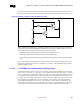
Figure 91 is an example power-on sequencing circuit that ensures the “2 V Rule” is obeyed. This circuit
uses a NPN (Q2) and PNP (Q1) transistor to ensure the 1.8-V supply tracks the 3.3-V supply. The NPN
transistor controls the current through PNP from the 3.3 V supply into the 1.8 V power plane by varying