
Mobile Intel Pentium 4 Processor - M and Intel 845MP/MZ Chipset Platform Design Guide

Mobile Intel
®
Pentium
®
4 Processor-M and Intel
®
845MP/845MZ Chipset Platform
Design Guide 183
R
12. System Design Checklist
12.1. Host Interface
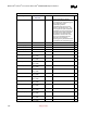
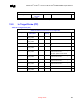
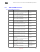
Table 68. Resistor Recommendations
Mobile Intel Pentium 4-M – Resistor Recommendations
Signal System Pull-up/
Pull-down
Ω
ΩΩ
Ω
Notes
9
99
9
H_A[35:3]# Connect A[31:3]# to
MCH-M. Leave
A[35:32]# as No
Connect
A[35:32]# are not supported by the
chipset. Has internal pull-up to
VCC_CORE
H_RESET# Pull-up to
VCC_CORE
51 Ω ±1% Place resistor < 0.1” from CPU
interface
H_IERR# Pull-up to
VCC_CORE
10 kΩ Required pull-up for noise reduction
H_FERR# Pull-up to
VCC_CORE
Use Voltage Translation Circuit
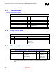
COMP[1:0] Pull-down to GND 51.1 Ω ±1% Individual pull-down resistor
CPU_VR_VID [4:0] Pull-up to V3.3S 1 kΩ
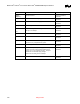
TESTHI0/BYPASSEN#
TESTHI1/H_ODT
TESTHI2/H_MCLK0
TESTHI3/ H_MCLK1
TESTHI4/ H_MCLK2
TESTHI5/ H_MCLK3
TESTHI8/H_BR3#
TESTHI9/H_BR2#
TESTHI10/H_BR1#
Pull-up to
VCC_CORE
The TESTHI pins should be tied to the
processor VCC using a matched
resistor, where a matched resistor has
a resistance value within +
20% of the
impedance of the board transmission
line traces. For example, If the trace
impedance is 50 ohm, then a value
between 40
Ω and 60Ω is required. The
TESTHI pins may use individual pull-
up resistors or be grouped together as
detailed below. A matched resistor
should be used for each group:
1) TESTHI[1:0]
2) TESTHI[5:2]
3) TESTHI[10:8]
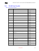
TESTHI6/ITPCLKOUT0
TESTHI7/ITPCLKOUT1
These pins as differential clock for an
ITP port designed on the motherboard.
if the ITPCLKOUT[1:0] pins are not
used then they may be connected
individually to VCC using matched
resistors or grouped with TESTHI[5:2]
with a single matched resistor. If they
are being used, individual termination
with 1-K
Ω resistors is required. Tying
ITPCLKOUT[1:0] directly to VCC or
sharing a pull-up resistor to VCC will
p
revent use of debu
g
inter
p
osers.