
Mobile Intel Pentium 4 Processor - M and Intel 845MP/MZ Chipset Platform Design Guide

Mobile Intel
®
Pentium
®
4 Processor-M and Intel
®
845MP/845MZ Chipset Platform
194 Design Guide
R
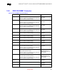
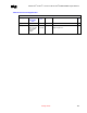
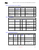
Table 78. Miscellaneous Signals
MCH-M – Miscellaneous Signals
Signal System Pull-up/Pull-down Ω
ΩΩ
Ω
Notes 9
99
9
AGP_RCOMP Connect to GND 36.5 Ω ± 1% For AGP devices
Referencing a 55-
Ω board impedance
HUB_RCOMP Pull-up to VCC1_8 36.5 Ω ± 1% Referencing a 55-Ω board impedance
SMRCOMP Connect to DDR Termination
Voltage (Vtt) through a 30.1
Ω ± 1% pull-up resistor.
Connect to a 0.1-µF
capacitor tied to ground.
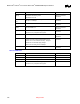
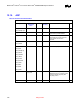
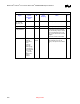
Table 79. Decoupling Recommendation
MCH-M – High Speed Decoupling Recommendations
Signal Configuration F
Qty
Notes 9
99
9
HUB_VREF Decouple to GND 0.01 µF 1 Place close to MCH-M
SM_VREF Decouple to GND 0.1 µF 1 Place as close as possible to the
MCH-M SDREF Input (J21/J9)
+VCC_CORE
(VTTFSB)
Decouple to GND
Decouple to GND
0.1 µF
10.0
µF
10
3
Distribute as close as possible to
MCH-M VTTFSB Quadrant
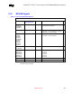
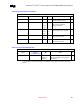
+V1.5S_MCH
(VCCAGP)
Decouple to GND
Decouple to GND
0.1 µF
10.0
µF
100
µF
6
2
1
Distribute as close as possible to
MCH-M AGP/Core Quadrant
+V1.8S_MCH
(VCCHL)
Decouple to GND
Decouple to GND
0.1 µF
10
µF
3
1
Distribute as close as possible to
MCH-M Hub Interface Quadrant
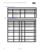
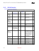
+V2.5 for MCH Decouple to GND
0.1 µF
22.0
µF
100
µF
150
µF
6(min)
2
3
Distribute as close as possible to
MCH-M System Memory Quadrant;
+V2.5 for DDR Decouple to GND
0.1 µF
100
µF
150
µF
9(min)
4
5
One 0.1 µF cap per power pin. Place
each cap close to DDR pin.
+V1.25V Decouple to GND
0.1 µF 54(min) Place one cap close to every 2 pull up
resistors termination.
NOTE: Please check on Low Frequency Decoupling values for the 2.5 DDR and 2.5 MCH-M.