
Mobile Intel Pentium 4 Processor - M and Intel 845MP/MZ Chipset Platform Design Guide

A
A
B
B
C
C
D
D
E
E
4 4
3 3
2 2
1 1
Optional cap: C652 value
6pF - 12pF if needed for
magnetics
Chassis GND
(should cover part
of magnetics)
Layout note:
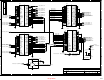
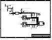
Place 100 Ohm resistor
close to Kinnereth
NOTE: Disable LAN_PHYCLK when
not using LAN Interface
LAN_PHYCLK
Enable
Disable
J12
Shunt (Default)
No Shunt
Layout note:
Transmit/Receive
pairs need to be 50
ohms
Bulk caps should be 4.7uF or higher.
If LAN is enabled,
PM_LANPWROK waits for
PM_PWROK to go high and
stays high in S3.
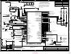
Kinnereth Testpoint Header
Magnetics and
LED resistors
are integrated
into RJ-45
NO_STUFF
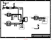
LAN Interface (Kinnereth)
27 42
845MP/MZ Platformm
Title
Sheet of
Project:
LAN_RB10
LAN_RB100
LAN_X2TP_LAN_TOUT
+V3_L_LAN
TP_LAN_ADV
LAN_CLK
LAN_TDP
LAN_TDN
LAN_RDP
LAN_SPDLED#
LAN_LILED#
LAN_RDN
LAN_TESTEN
LAN_ACTLED#
LAN_TCK
PM_LANPWROK
16,29
LAN_RST15
LAN_TXD015
LAN_TXD215
LAN_TXD115
LAN_JCLK15
LAN_RXD215
LAN_RXD015
LAN_RXD115
+V3.3_LAN
+V3.3 14,17,19,21,24,29,34,36,40
+V3.3_LAN
+V3.3_LAN
C41
22PF
R2
NO_STUFF_0.01_1%
12
R4 619_1%
R3 549_1%
C11
4.7UF
12
C23
22PF
J12
1 2
Y1
25MHZ
41
R7
100_1%
R426
10K
R6
120
C4
0.1UF
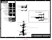
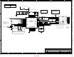
Platform LAN
Connect
U4
82562ET
48
1
47
46
2
45
3
44
43
4
42
5
41
40
6
39
7
38
37
8
36
9
35
34
10
33
11
32
31
12
30
13
29
28
14
27
15
26
25
16
17
18
1920
21
22 23
24
VSS1
VCC1
X2
X1
VCCA_1
JTXD2
VSSA_2
JTXD1
JTXD0
RBIAS10
JRSTSYNC
RBIAS100
ADV10
VCCP_1
VSSA2
JCLK
VCCA2
VSSP_1
JRXD2
VSS2
VCCP_2
VCCT_1
JRXD1
JRXD0
TDP
VSSP_2
TDN
ACTLED
SPDLED
VCCT_2
ISOL_TCK
VSS3
ISOL_EX
ISOL_TI
VCCT_3
LILED
RDP
TOUT
VCC2
RDN
VCCT_4
VSS4
VCCR1VSSR1
TESTEN
VSSR2 VCCR2
VSS5
C3
0.1UF
C40
0.1UF
C42
0.1UF
C8
0.1UF
GRN
YLW
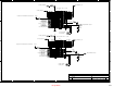
J10A
STACKED_RJ45_USB
9
10
11
12
13
14
15
16
17
18
19
20
28
27
26
25
24
23
22
21
TDP
TDN
RDP
TDC2
TDC1
RDN
RXC
GND9
LED_PWR
SPEED LED
ACT_LED
LINK_LED
GND1
GND2
GND3
GND4
GND5
GND6
GND7
GND8
J9
1 2
C1
10PF
NO_STUFF_603275-109
Q2
BSS138
3
1
2
R316
100
C12
4.7UF
12
C39
4.7UF
12
L1
4.7UH
1 2
237
Design Guide