
Mobile Intel Pentium 4 Processor - M and Intel 845MP/MZ Chipset Platform Design Guide


Mobile Intel
®
Pentium
®
4 Processor-M and Intel
®
845MP/845MZ Chipset Platform
32 Design Guide
R
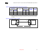
3.4.3. Common Clock (CC) AGTL+ Signals
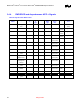
Table 7. Processor System Bus Control Signal Routing Guidelines
Signal Names
Routing Trace Length
(Pin-to-Pin)
CPU
Intel
845MP/845MZ
Topology
Max
(inches)
Min
(inches)
Nominal Board
Impedance (ohms)
Width & spacing
(mils)
RESET# CPURST# Stripline 10.0 1.5 55 ± 15% 4 & 8
BR0# BR0# Stripline 10.0 1.5 55 ± 15% 4 & 8
BNR# BNR# Stripline 10.0 1.5 55 ± 15% 4 & 8
REQ[4:0]# HREQ[4:0]# Stripline 10.0 1.5 55 ± 15% 4 & 8
BPRI# BPRI# Stripline 10.0 1.5 55 ± 15% 4 & 8
DEFER# DEFER# Stripline 10.0 1.5 55 ± 15% 4 & 8
LOCK# HLOCK# Stripline 10.0 1.5 55 ± 15% 4 & 8
TRDY# HTRDY# Stripline 10.0 1.5 55 ± 15% 4 & 8
DRDY# DRDY# Stripline 10.0 1.5 55 ± 15% 4 & 8
ADS# ADS# Stripline 10.0 1.5 55 ± 15% 4 & 8
DBSY# DBSY# Stripline 10.0 1.5 55 ± 15% 4 & 8
HIT# HIT# Stripline 10.0 1.5 55 ± 15% 4 & 8
HITM# HITM# Stripline 10.0 1.5 55 ± 15% 4 & 8
RS[2:0]# RS[2:0]# Stripline 10.0 1.5 55 ± 15% 4 & 8
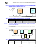
NOTE: Trace width of 4 mils and trace spacing of 8 mils within signal groups. Entire trace for each signal routed on
one layer (recommended) RESET# and BR0# are CC AGTL+ signals without ODT (On die termination). For
these signals Rtt should be placed near CPU: L2<= 0.5 inches. Rtt = 51.1 ±1%. Routing these signals to 4.0
inches ± 0.5 inches should maximize the setup and hold margin parameters while adhering to expected
mobile solution design constraints.
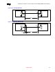
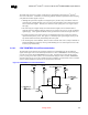
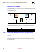
3.4.3.1. CC Topology with ODT
ODT Compensation Resistors:
Pentium 4: R_comp = 51.1 ± 1% ohms (Pins L24 and P1 – Pulled to ground through resistor)
Intel 845MP/845MZ: R_comp = 24.9 ± 1% ohms (Pins AC2 and AC13 - Pulled to ground through
resistor)