
Mobile Intel Pentium 4 Processor - M and Intel 845MP/MZ Chipset Platform Design Guide


Mobile Intel
®
Pentium
®
4 Processor-M and Intel
®
845MP/845MZ Chipset Platform
36 Design Guide
R
3.4.4.1.1. Topology #1: Asynchronous AGTL+ Signals Driven by the Processor; FERR#,
IERR#, PROCHOT# and THRMTRIP#
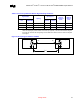
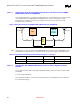
These signals should adhere to the following routing and layout recommendations. Figure 9 illustrates the
recommended topology. If THRMTRIP# and PROCHOT# are routed to external logic, voltage
translation may be required to avoid excessive voltage levels at the processor and to meet input
thresholds for the external logic.
Figure 9. Routing Illustration for FERR#, IERR#, PROCHOT#, and THRMTRIP#
CPU
ICH3-M
(or sys.
receiver)
Voltage
Translator
L2
L2
Vtt_CPU Vcc_Rcvr
L3L3
Rtt_CPU
Rtt_Rcvr
L1
Note: If the design is not using the recommended THRMTRIP# latch circuit in Figure 9, THRMTRIP# can be
routed through a Voltage Translator to a system logic that can provide the equivalent latching function.
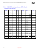
Table 9. Layout Recommendations for Miscellaneous Signals – Topology 1
L1 L2 L3 Rtt
1.5" - 14.0" 1.1" max 3.0" max Rtt_CPU = 56 ohms ± 5%
Rtt_Rcvr = 300 ohms ± 5%
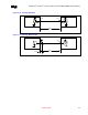
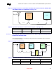
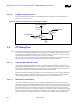
3.4.4.1.2. Topology #2, #2A: PWRGOOD and Asynchronous AGTL+ Signals Driven by
ICH3-M
Top. #2 signals: LINT1/INTR, LINT0/NMI, CPUPERF#, DPSLP#, SLP#, STPCLK#, IGNNE#, SMI#
and A20M#.
Top. #2A signal: PWRGOOD.
These signals should adhere to the following routing and layout recommendations. Figure 10 illustrates
the recommended topology.