
Mobile Intel Pentium 4 Processor - M and Intel 845MP/MZ Chipset Platform Design Guide

Mobile Intel
®
Pentium
®
4 Processor-M and Intel
®
845MP/845MZ Chipset Platform
42 Design Guide
R
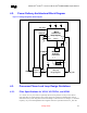
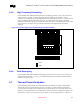
general desired filter topology is shown in Figure 14. Not shown in the core is parasitic routing and
excluded from the external circuitry are parasitics associated with each component.
Figure 14. Typical VCCIOPLL, VCCA, and VSSA Power Distribution
VCC_VID
VCCA
VSSA
VCCIOPLL
Processor
Core
PLLs
Motherboard
pkg
c2
1 µF
33 µF
33 µF
4.7 µH
4.7 µH
C
A
C
IO
The function of the filter is two-fold. It protects the PLL from external noise through low-pass
attenuation. It also protects the PLL from internal noise through high-pass filtering. In general, the low-
pass description forms an adequate description for the filter. For simplicity this document will address
the recommendation for the V
CCA
filter design. The same characteristics and design approach is
applicable for the V
CCIOPLL
filter design.
Note: The 1-µF package capacitor in Figure 14 does not exist on the Mobile Intel Pentium 4 Processor-M in
the 478-pin package. It is present for the Mobile Intel Pentium 4 Processor-M only.
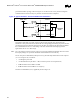
The AC low-pass recommendation, with input at VCC_VID and output measured across the capacitor
(C
A
or C
IO
in Figure 14), is as follows:
• < 0.2 dB gain in pass band
• < 0.5 dB attenuation in pass band < 1 Hz (see DC drop in next set of requirements)
• 34 dB attenuation from 1 MHz to 66 MHz
• 28 dB attenuation from 66 MHz to core frequency
The filter recommendation (AC) is graphically shown in Figure 15.