
Mobile Intel Pentium 4 Processor - M and Intel 845MP/MZ Chipset Platform Design Guide

Mobile Intel
®
Pentium
®
4 Processor-M and Intel
®
845MP/845MZ Chipset Platform
Design Guide 43
R
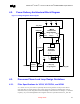
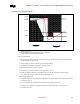
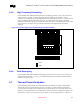
Figure 15. Filter Recommendation
0 dB
-28 dB
-34 dB
0.2 dB
forbidden
zone
-0.5 dB
forbidden
zone
1 MHz 66 MHz
f
core
f
peak1 HzDC
passband
high frequency
band
NOTES:
1. Diagram not to scale.
2. No specification for frequencies beyond fcore (core frequency).
3. fpeak, if existent, should be less than 0.05 MHz.
Other recommendations:
• Capacitors for the filter can be any value between 22 µF and 100 µF as long components with ESL
≤ 5 nH and ESR < 0.3 Ω are used.
• Values of either 4.7 µH or 10 µH may be used for the inductor.
• Use shielded type inductors to minimize magnetic pickup
• Filter should support DC current > 60 mA
• DC voltage drop from VCC_CPU to VCCA should be < 60 mV
• In order to maintain a DC drop of less than 60 mV, the total DC resistance of the filter from
VCC_VID to the processor socket should be a maximum of 1 µ.
Other routing requirements:
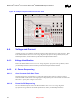
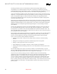
• C should be within 600 mils of the VCCA and VSSA pins. An example of the component placement
is shown in Figure 16
• VCCA route should be parallel and next to VSSA route (minimize loop area)
• A minimum of a 12-mil trace should be used to route from the filter to the processor pins.
• L should be close to C