
Mobile Intel Pentium 4 Processor - M and Intel 845MP/MZ Chipset Platform Design Guide

Mobile Intel
®
Pentium
®
4 Processor-M and Intel
®
845MP/845MZ Chipset Platform
46 Design Guide
R
response of the processor, it is necessary to properly place bulk and high frequency capacitors close to
the processor power and ground pins.
4.6.1. Transient Response
The inductance of the motherboard power planes slows the voltage regulator’s ability to respond quickly
to a current transient. Decoupling a power plane can be broken into several independent parts. The
closer to the load the capacitor is placed, the more stray inductance is bypassed. By bypassing the
inductance of leads, power planes, etc., less capacitance is required. However, areas closer to the load
have less room for capacitor placement. Therefore, tradeoffs must be made.
The processor causes very large switching transients. These sharp surges of current occur at the
transition between low power states and the normal operating states. It is the responsibility of the system
designer to provide adequate high frequency decoupling to manage the highest frequency components of
the current transients. Larger bulk storage capacitors supply current during longer lasting changes in
current demand.
All of this power bypassing is required due to the relatively slow speed at which a DC-to-DC converter
can respond. A typical voltage converter has a reaction time on the order of 1 to 100
µs while the
processor’s current steps are on the order of 30 to 40 ns. High Frequency decoupling is typically done
with ceramic capacitors with a very low ESR. Because of there low ESR, these capacitors can act very
quickly to supply current at the beginning of a transient event. However, because the ceramic capacitors
are small, i.e. they can only store a small amount of charge, Bulk capacitors are needed too. Bulk
capacitors are typically polarized with high capacitance values and unfortunately higher ESRs. The
higher ESR of the Bulk capacitor limits how quickly it can respond to a transient event. The Bulk and
HF capacitors working together can supply the charge needed to stay in regulator before the regulator
can react during a transient.
A load change transient occurs when coming out of or entering a low power state. These are not only
quick changes in current demand, but also long lasting average current requirements. This occurs when
the processor enters different power modes by stopping and starting it’s internal clock. The processor
current requirements can change by as much as 70% (±10%) of the maximum current very quickly.
4.6.2. Processor Voltage Plane
Power must be distributed as a plane. This plane can be constructed as an island on a layer used for
other signals, on a supply plane with other power islands, or as a dedicated layer of the PCB. Processor
power should never be distributed by traces alone. Intel recommends that all layers of the stack-up be
used for processor power and ground routing.
Due to the fact that the processor voltage is unique to most system designs, a voltage island is the most
cost-effective means of distributing power to the processor. This island from the source of power to the
load should not have any breaks so as to minimize inductance in the plane. It should also completely
surround all of the pins of the source and all of the pins in the power pin area of the processor.
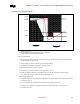
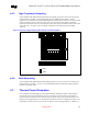
The bulk capacitors and the high frequency capacitors should be placed as close to the processor as
possible and in the path of current flow. The processor socket has 478 pins with 50-mil pitch. The
routing of these signals, power, and ground pins will require many vias. These vias cause a “Swiss
Cheese” effect in the power and ground planes beneath the processor resulting in increased inductance
and resistance of these planes. This increase in impedance can choke off the high current carrying
channel of the voltage regulator. In order to provide the best path through the via field, it is
recommended that vias are shared for every two processor ground pins.