
Mobile Intel Pentium 4 Processor - M and Intel 845MP/MZ Chipset Platform Design Guide

Mobile Intel
®
Pentium
®
4 Processor-M and Intel
®
845MP/845MZ Chipset Platform
Design Guide 47
R
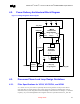
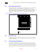
4.6.3. High Frequency Decoupling
System motherboards should include high frequency decoupling capacitors as close to the socket power
and ground pins as possible. A total of thirty-eight 10.0-
µF, X5R/X7R, 1206 package, ceramic
capacitors are recommended to provided high frequency decoupling for the processor. Ten of these 1206
capacitors should be placed in the socket cavity area. Fourteen of these 1206 capacitors should be
placed on the north side of the cavity and fourteen of these 1206 capacitors should be placed on the south
side of the cavity. See Figure 19 for an example on placement of the high frequency decoupling
capacitors.
Figure 19. Processor High Frequency Decoupling Placement Example
.
VCC
VSS
4.6.4. Bulk Decoupling
System motherboards should include bulk-decoupling capacitors as close to the processor socket power
and ground pins as possible (<1.0 inch). The maximum Equivalent Series Resistance (ESR) should be
equal to or less than 2.5 m
Ω.
4.7. Thermal Power Dissipation
Power dissipation has traditionally been a thermal/mechanical challenge for mobile system designers.
The amount of current required from the processor power delivery circuit and the heat generated by
processors has increased as processor frequencies go up and the silicon process geometry shrinks. The
package of any integrated device can only dissipate so much heat into the surrounding environment. The
temperature of a device, such as a processor power delivery circuit-switching transistor, is a balance of