
Mobile Intel Pentium 4 Processor - M and Intel 845MP/MZ Chipset Platform Design Guide

Mobile Intel
®
Pentium
®
4 Processor-M and Intel
®
845MP/845MZ Chipset Platform
Design Guide 59
R
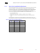
5.2.1.2. Strobe to Clock Length Matching Requirements
The data strobe signals must be 1.0 inch to 2.0 inches shorter than their associated differential clock
pairs.
Length matching equation for SO-DIMM0:
X
1
=SCK/SCK#[2:0]
Y
1
=SDQS[8:0] = MCH-M package + L1 + L2 of Figure 21 where,
( X
1
– 2.0” ) ≤ Y
1
≤ ( X
1
– 1.0” )
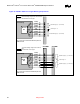
Length matching equation for SO-DIMM1:
X
2
=SCK/SCK#[5:3]
Y
2
= SDQS[8:0] = MCH-M Package + L1 + L2 + L3 of Figure 21 where,
( X
2
– 2.0” ) ≤ Y
2
≤ ( X
2
– 1.0” )
For example if the total clock length of SCK/SCK#[2:0](X
1
) is 3.5 inches then the length of all data
strobe signal routing to SO-DIMM0 must be between 1.5 inches to 2.5 inches, if SCK/SCK#[5:3](X
2
) is
4.5 inches then the length of all control signal route to SO-DIMM1 must be between 2.5 inches to 3.5
inches.
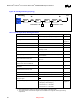
• The MCH-M package lengths for clocks and strobes must be taken into account for routing length
matching.
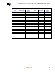
• Refer to Section Table 23 or the Pentium
®
4 Processor-M in the 568 Pin Package and
845MP/845MZ Chipset Platform Trace Length Calculator for package trace length data.
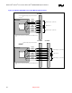
Figure 22 depicts the length matching requirements between the data strobe signals and the clock signals.