
Mobile Intel Pentium 4 Processor - M and Intel 845MP/MZ Chipset Platform Design Guide

Mobile Intel
®
Pentium
®
4 Processor-M and Intel
®
845MP/845MZ Chipset Platform
Design Guide 69
R
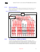
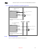
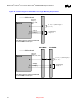
Figure 29. Referencing Plane Stack-up
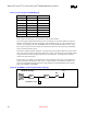
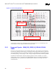
5.2.3.1.2. Command Group Signal Length Matching Requirements
The command signals must be 1.0 inch to 3.0 inches shorter than their associated differential clock pairs
SCK/SCK#[5:0].
Note that these requirements may change in a later revision of the design guide based on a post silicon
simulation analysis.
Length matching equation for SO-DIMM0:
X
1
=SCK/SCK#[2:0]
Y
1
=L1 of Figure 30 where,
( X
1
– 3.0” ) ≤ Y
1
≤ ( X
1
– 1.0 inch )
Length matching equation for SO-DIMM1:
X
2
=SCK/SCK#[5:3]
Y
2
=L1+L2+L3 of Figure 30where,
( X
2
– 3.0 inches) ≤ Y
2
≤ ( X
2
– 1.0 inch ). For example if the clock length of SCK/SCK#[2:0](X
1
) is 5.0
inches then the length of all command signal routing to SO-DIMM0 must be between 2.0 inches to 4.0
inches, if SCK/SCK#[5:3](X
2
) is 5.5 inches then the length of command signal routing to SO-DIMM1
must be between 2.5 inches to 4.5 inches.
Caution: The MCH-M package lengths do not need to be taken into account for routing purposes. Figure 30 below
depicts the length matching requirements between the command signals and the clock signals.