
Mobile Intel Pentium 4 Processor - M and Intel 845MP/MZ Chipset Platform Design Guide

Mobile Intel
®
Pentium
®
4 Processor-M and Intel
®
845MP/845MZ Chipset Platform
82 Design Guide
R
External trace lengths should be minimized. All internal and external signals should be ground
referenced to keep the path of the return current continuous.
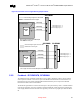
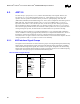
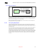
The diagrams and table below depicts the recommended topology and layout routing guidelines for the
DDR-SDRAM feedback signal.
Figure 40. DDR Feedback (RCVEN#) Routing Topology
MCH-M MCH-M
A
RCVENOUT#
Ball
RCVENIN#
Ball
B
A
Internal Layer
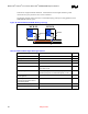
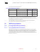
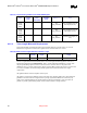
Table 22. DDR Feedback Signal Routing Guidelines
Parameter Routing Guidelines Figure
Signal Group Feedback – RCVENOUT# and RCVENIN#
Topology Point to Point
Reference Plane Ground Referenced
Characteristic Trace Impedance (Zo) 55 Ω ± 15%
Trace Width Inner layers= 4 mils
Outer layers= 5mils
Group Spacing Isolation spacing from another DDR signal group = 10 mils
Isolation spacing from non-DDR related signals = 10 mils
Trace Length A – MCH-M Signal Ball to
MCH-M Signal Via
Max = 40 mils Figure 40
Total Length A + B – MCH-M
RCVENOUT# Signal Ball to MCH-M
RCVENIN# Signal Ball
Must equal 1000 mils ± 10 mils Figure 40
Maximum via Count per signal 2
Length Matching Requirements None