
Mobile Intel Pentium 4 Processor - M and Intel 845MP/MZ Chipset Platform Design Guide
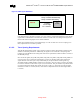

Mobile Intel
®
Pentium
®
4 Processor-M and Intel
®
845MP/845MZ Chipset Platform
Design Guide 87
R
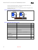
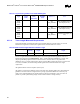
These signals are used in 4X AGP mode ONLY.
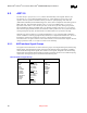
Table 25. AGP 2.0 Data/Strobe Associations
Data Associated Strobe in 1X Associated
Strobe in 2X
Associated
Strobes in 4X
AD[15:0] and C/BE[1:0]# Strobes are not used in 1X mode. All
data is sampled on rising clock edges.
AD_STB0 AD_STB0,
AD_STB0#
AD[31:16] and C/BE[3:2]# Strobes are not used in 1X mode. All
data is sampled on rising clock edges.
AD_STB1 AD_STB1,
AD_STB1#
SBA[7:0] Strobes are not used in 1X mode. All
data is sampled on rising clock edges.
SB_STB SB_STB,
SB_STB#
Throughout this section, the term data refers to AD[31:0], C/BE[3:0]#, and SBA[7:0]. The term strobe
refers to AD_STB[1:0], AD_STB#[1:0], SB_STB, and SB_STB#. When the term data is used, it refers
to one of the three sets of data signals, as in Table 24. When the term strobe is used, it refers to one of the
strobes as it relates to the data in its associated group.
The routing guidelines for each group of signals (1X timing domain signals, 2X/4X timing domain
signals, and miscellaneous signals) will be addressed separately.
6.3. AGP Routing Guidelines
6.3.1. 1X Timing Domain Routing Guidelines
6.3.1.1. Trace Length Requirements for the AGP 1X
This section contains information on the 1X Timing Domain Routing Guidelines. The AGP 1X timing
domain signals (refer to Table 24) has a maximum trace length of 9.5 inches. The target impedance is 55
ohm, with plus and minus fifteen percent tolerance. This maximum applies to ALL of the signals listed as
1X timing domain signals in Table 25. In addition to this maximum trace length requirement (refer to
Table 27 and Table 28) these signals must meet the trace spacing and trace length mismatch requirements
in Sections 6.3.1.2 and 6.3.1.3.