
Mobile Intel Pentium 4 Processor - M and Intel 845MP/MZ Chipset Platform Design Guide

Mobile Intel
®
Pentium
®
4 Processor-M and Intel
®
845MP/845MZ Chipset Platform
Design Guide 89
R
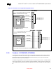
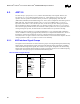
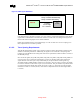
Figure 41. AGP Layout Guidelines
(Line:Space)
AGP
Controller
MCH-M
Always 1:2 Strobe to Strobe# Routing
Always 1:3 Strobe to Data Routing
1:3 routing
6.0” max length
+/-0.1” mismatch
If the AGP interface is less than 6.0 inches, a 1:2 trace spacing is required for 2X/4X lines. These 2X/4X
signals must be matched their associated strobe within
± 0.1 inches. This is for designs that require less
than 6 inches between the graphics device and the MCH-M.
Reduce line length mismatch to ensure added margin. In order to reduce trace to trace coupling (cross
talk), separate the traces as much as possible.
6.3.2.2. Trace Spacing Requirements
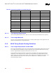
AGP 2X/4X timing domain signals (refer to Table 25) must be routed as documented in Table 28. They
should be routed using 4-mil traces. Additionally, the signals can be routed with 5-mil spacing when
breaking out of the MCH-M. The routing must widen to the requirement in Table 28 within 0.3 inches of
the MCH-M package.
Since the strobe signals (AD_STB0, AD_STB0#, AD_STB1, AD_STB1#, SB_STB, and SB_STB#) act
as clocks on the source synchronous AGP interface, special care should be taken when routing these
signals. Because each strobe pair is truly a differential pair, the pair should be routed together (e.g.
AD_STB0 and AD_STB0# should be routed next to each other). The two strobes in a strobe pair should
be routed on 4-mil traces with 8 mils of space (1:2) between them. This pair should be separated from the
rest of the AGP signals (and all other signals) by at least 15 mils (1:3). The strobe pair must be length
matched to less than
± 0.1 inches (that is, a strobe and its compliment must be the same length within ±
0.1 inches).