
Mobile Intel Pentium 4 Processor - M and Intel 845MP/MZ Chipset Platform Design Guide


Mobile Intel
®
Pentium
®
4 Processor-M and Intel
®
845MP/845MZ Chipset Platform
Design Guide 99
R
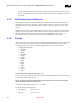
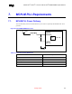
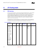
Figure 45. Single HUBREF Voltage Divider
MCH-M
HUBREF
ICH3-M
C1
C2C1
R1
R2
4"4"
1.8V
HIREF
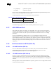
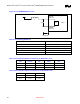
Figure 46. Locally Generated HUBREF Divider
ICH3-M
C2
R1
R2
<4"
1.8V
HIREF
MCH-M
C2
R1
R2
<4"
1.8V
HUBREF
NOTE: There is no C1.
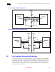
8.5. Hub Interface Decoupling Guidelines
To improve I/O power delivery, use two 0.1-µF capacitors per each component (i.e. the ICH3-M and
MCH-M). These capacitors should be placed within 150 mils from each package, adjacent to the rows
that contain the hub interface. If the layout allows, wide metal fingers running on the VSS side of the
board should connect the VCC1_8 side of the capacitors to the VCC1_8 power balls. Similarly, if layout
allows, metal fingers running on the VCC1_8 side of the board should connect the groundside of the
capacitors to the VSS power balls.