
Thermally Advantaged Tested Chassis Guide


2.2 Thermally Advantaged Chassis Typical Airflow
Pattern
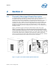
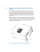
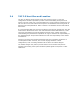
Figure 2 depicts the intended airflow pattern with the side vent. This system has a
92mm rear system fan and 80mm power supply fan. Both fans exhaust (blow out)
from the chassis, thereby providing intake airflow for internal system component
cooling. This fan configuration causes depressurization of the chassis interior with
respect to the outside air. As a result, all other chassis openings become intake vents.
The primary intake vent defined in this design guide is the side panel vent however
other smaller vent locations such as the front bezel and add-in card areas can be
beneficial as well.
Airflow balancing is critical to ensure the adequate cooling of all system components.
Without proper balancing, some components may operate cooler than required while
others may operate in a higher temperature environment. Proper airflow balancing is
difficult to manage but done properly, should allow all system components to operate
within the recommended temperature range. Ensuring balanced airflow is the
responsibility of the chassis designer.
Figure 2. Thermally Advantaged Chassis Typical Airflow Pattern