
Voltage Regulator-Down (VRD) 10.0 Design Guide Addendum


R
VRD Design Guide Addendum
6 Output Indicators
6.1 Processor Power Good Output (Vcc_PWRGD)
(PROPOSED)
The VRD should provide a power-good signal, which remains in the low state until a maximum
of 10 milliseconds after the output voltage reaches the range specified in Section 2.2. The signal
should then remain asserted when the VRD is operating, except for fault or shutdown conditions.
Vcc_PWRGD must not be de-asserted during the Dynamic VID operation.
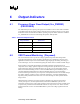
Table 7. Power Good Specifications
Design Parameter Specification
Signal Type
Open-collector or equivalent
Voltage Range
5.5 V (maximum) in open state
Minimum I
OL
4 mA
Maximum V
OL
0.4 V
6.2 VRD Thermal Monitoring (Proposed)
This section describes how to protect the voltage regulator design from heat damage while
supporting thermal design current (VR TDC) specifications. It is included for reference and is
applicable to Pentium 4 processor Extreme Edition supporting Hyper-Threading Technology in
socket 478 designs. It is not recommend integrating this feature into Vcc PWM controller designs.
Each customer is responsible for identifying maximum temperature specifications for all
components in the voltage regulator design and ensuring that these specifications are not violated
while continuously drawing specified VR TDC levels. In the event of a catastrophic thermal
failure, the thermal monitoring circuit is to assert the PROCHOT# signal immediately prior to
exceeding maximum motherboard and component thermal ratings to prevent heat damage.
Assertion of this signal will lower processor power consumption and reduce current draw through
the voltage regulator, resulting in lower component temperatures. Assertion of PROCHOT#
degrades system performance and must never occur when drawing less than specified thermal
design current.
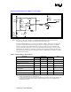
VRD temperature violations can be detected using a thermal sensor and associated control
circuitry (see Figure 6). For this implementation, a thermistor (THMSTR) is placed in the
temperature sensitive region of the voltage regulator. The location must be chosen carefully and is
to represent the position where initial thermal violations are expected to occur. When exceeded,
the thermal monitor circuit is to initiate PROCHOT# to protect the voltage regulator from heat
damage.