
Voltage Regulator-Down (VRD) 10.0 Design Guide Addendum

R
VRD Design Guide Addendum
Contents
1 Introduction ......................................................................................................................... 7
1.1 Terminology............................................................................................................ 7
2 Processor Voltage Requirements ....................................................................................... 9
2.1 Voltage and Current (REQUIRED)......................................................................... 9
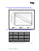
2.2 Load Line Definitions (REQUIRED) ....................................................................... 9
2.3 TOB: Voltage Tolerance Band (REQUIRED)...................................................... 11
2.3.1 Sources of Voltage Deviation & Input Parameters ............................... 11
2.3.2 TOB: Tolerance Band Calculation ........................................................ 12
2.3.2.1 Inductor RDC Current Sense TOB Calculations ................. 13
2.3.2.2 Resistor Current Sense TOB Calculations.......................... 13
2.3.2.3 FET RDS-ON Current Sense TOB Calculations................. 14
2.4 VRD Thermal Compensation (REQUIRED)........................................................ 14
2.5 Electrical & Thermal Current Support (EXPECTED) ........................................... 15
2.6 Stability (EXPECTED) .......................................................................................... 15
2.7 Processor Power Sequencing (REQUIRED) ....................................................... 15
2.8 Processor Vcc Overshoot (REQUIRED)............................................................. 16
2.9 Desktop VRD Output Filter (REQUIRED) ........................................................... 18
2.10 Shutdown Response (REQUIRED)...................................................................... 18
3 Control Inputs.................................................................................................................... 19
3.1 Output Enable (REQUIRED)................................................................................ 19
3.2 Voltage Identification (VID [5:0]) (REQUIRED).................................................... 19
3.3 Differential Remote Sense Input (REQUIRED)................................................... 21
4 Input Voltage and Current................................................................................................. 23
4.1 Input Voltages (EXPECTED)................................................................................ 23
4.2 Load Transient Effects on Input Current (EXPECTED) ....................................... 23
5 Output Protection .............................................................................................................. 25
5.1 Over-Voltage Protection (OVP) (PROPOSED)................................................... 25
5.2 Over-Current Protection (OCP) (PROPOSED)................................................... 25
6 Output Indicators...............................................................................................................27
6.1 Processor Power Good Output (Vcc_PWRGD) (PROPOSED)........................... 27
6.2 VRD Thermal Monitoring (Proposed).................................................................. 27
6.3 Load Indicator Output (PROPOSED).................................................................. 29
7 VccVID Voltage ................................................................................................................. 31
7.1 VccVID Voltage (PROPOSED) ........................................................................... 31