
Voltage Regulator-Down (VRD) 10.0 Design Guide Addendum

R
VRD Design Guide Addendum
2 Processor Voltage Requirements
2.1 Voltage and Current (REQUIRED)
A six-bit VID code supplied by the processor to the VRD determines a reference output voltage,
as described in Section 3.2. The load lines in Section 2.2 show the relationship between Vcc and
Icc for the processor, and the tolerances between Vcc-minimum and Vcc-maximum.
Intel performs exhaustive testing against multiple software applications and software test vectors
to identify valid processor Vcc operating ranges. Failure to satisfy the load line, load line
tolerance band, and overshoot specifications (section 2.2, 2.3 and 2.8) may cause data corruption,
intermittent system lockup and lead to premature processor failure. In addition this could void the
Pentium 4 processor Extreme Edition supporting Hyper-Threading Technology in socket 478
processor warranty.
2.2 Load Line Definitions (REQUIRED)
The following load lines contain DC and transient-droop data as well as maximum and minimum
voltage levels. The voltages are measured at the processor-socket Vcc and Vss pins between the
voltage regulator and the processor cavity. For standard layouts these measurements are taken at
Vcc pin AC14 and Vss pin AC15. In some instances these two pins will not be located between
the voltage regulator and the processor cavity. In these cases, select pins that are centered in the
pin field between the cavity and the voltage regulator. It is recommended to place test points to
these pins on the bottom side of the motherboard to enable load line tuning and validation.
Table 1: Intel
®
Pentium
®
4 processor Extreme Edition Supporting Hyper-Threading
Technology Power Delivery Specifications
Iccmax VR TDC Dynamic Icc Socket Load
Line
VRD Tolerance
Band
Max VID
91A 80A 70A 1.50mOhms +/- 19mV 1.600
1
NOTE:
1. Maximum projected Pentium 4 processor Edition supporting Hyper-Threading Technology VID
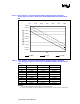
The following figures and tables show load-line voltage offsets and current levels based on the
VID settings specified in Table 6. The following equations for the load lines are valid for the
range of load current from 0 A to 91 A.
Intel
®
Pentium
®
4 processor Extreme Edition Supporting Hyper-Threading
Technology Load Line Equations
V
MAX
load line: Vcc = VID – (1.50 mOhms * Icc)
V
TYP
load line: Vcc = VID – 0.019 V – (1.50 mOhms * Icc)
V
MIN
load line: Vcc = VID – 0.038 V - (1.50 mOhms * Icc)