
Voltage Regulator-Down (VRD) 10.0

Processor Voltage Requirements
R
VRD Design Guide 13
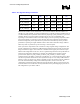
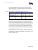
Table 5. Mapping of Intel Processors to VRD Configurations
Processor VR Configuration
Intel® Pentium® 4 Processor 478_VR_CONFIG_C
Intel® Pentium® 4 Processor with 512-KB L2 Cache on 0.13 Micron
Process at 3.40 GHz
478_VR_CONFIG_D
Intel® Pentium® 4 Processor Extreme Edition Supporting Hyper-
Threading Technology
1
Process
478_VR_CONFIG_D
478_VR_CONFIG_A
Intel® Pentium® 4 Processor on 90 nm Process
1
478_VR_CONFIG_B
Intel® Celeron® Processor on 0.13 Micron Process in the 478-Pin
Package
3
478_VR_CONFIG_C
NOTES:
1. Processor functions under multiple VR configurations. Consult the processor’s data sheet for the
required configuration.
2. Compatible with most systems designed to Iccmax=70 A. Consult the product datasheet for the actual
value of Iccmax.
3. Consult product data sheet for actual Iccmax value
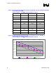
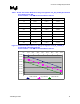
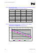
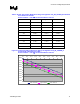
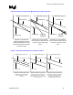
The following tables and figures show minimum and maximum voltage boundaries for each
loadline design configuration defined in Table 4. Typical loadline orientation is provided for
design reference; designs should calibrate the loadline to the mean of the tolerance band –
centered in the loadline window. Note that Intel processors are shipped with a multiple VID
values. A single loadline chart and figure for each VRD design configuration can represent
functionality for each value. Tables and figures presented as voltage deviation from VID provide
the necessary information to identify voltage requirements at any reference VID. This avoids the
redundancy of publishing tables and figures for each of the multiple cases.