
Voltage Regulator-Down (VRD) 10.1 Design Guide


Processor Vcc Requirements
R
Design Guide 13
2 Processor Vcc Requirements
2.1 Voltage and Current (REQUIRED)
A six-bit VID code supplied by the processor to the VRD determines a reference output voltage
as described in Section 6.2. The socket load lines in Section 2.2 show the relationship between
Vcc and Icc for the processor at the motherboard-socket interface.
Intel performs exhaustive testing against multiple software applications and software test vectors
to identify valid processor Vcc operating ranges. Failure to satisfy the socket load line, load line
tolerance band, and overshoot voltage specifications (Sections 2.3 and 2.7) may invalidate Intel
warranties and lead to premature processor failure, intermittent system lock-up, and/or data
corruption.
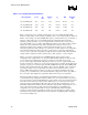
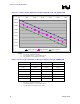
2.2 Socket Loadline Definitions (REQUIRED)
To ensure processor reliability and performance, platform DC voltage regulation and transient-
droop noise levels must always be contained within the Vccmin and Vccmax socket load line
boundaries (known as the load line window). Socket load line compliance must be guaranteed
across 3-σ component manufacturing tolerances, thermal variation, and age degradation. Socket
load line boundaries are defined by the following equations in conjunction with the Vcc regulator
design parameter values defined in Table 2-1. Load line voltage tolerance is defined in Section
2.3. In these equations, VID, R
LL
, and TOB are known. Plotting Vcc while varying Icc from 0 A
to Iccmax establishes the Vccmax and Vccmin socket load lines. Vccmax establishes the
maximum DC socket load line boundary. Vccmin establishes the minimum AC and DC voltage
boundary. Short transient bursts above the Vccmax load line are permitted; this condition is
defined in Section 2.7.
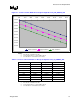
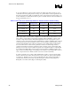
Table 2-1. Socket Load Line Equations
Socket load line Equation
Equation 2-1: Vccmax Socket load line
Vcc = VID – (R
LL
* I
cc
)
Equation 2-2: Vcctyp Socket load line
Vcc = VID – TOB - (R
LL
* I
cc
)
Equation 2-3: Vccmin Socket load line
Vcc = VID – 2*TOB - (R
LL
* I
cc
)
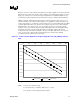
Socket load line recommendations are established to provide guidance for satisfying processor die
load line specifications, which are defined in processor datasheets. Die load line requirements
must be satisfied at all times and may require adjustment in the socket load line value.