
Voltage Regulator-Down (VRD) 10.1 Design Guide

Processor Vcc Requirements
R
24 Design Guide
2.3.2 TOB: Tolerance Band Calculation
Reference TOB equations for each major current sense topology are provided in the next three
subsections. Equations are presented in a manner for simple entry into a spreadsheet to simplify
TOB calculation and design iterations.
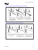
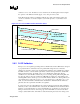
2.3.3 Inductor RDC Current Sense TOB Calculations
Inductor sensing is the best general approach to satisfying the tolerance band requirements. TOB
can be directly controlled by selecting output inductors and integrating capacitors of sufficient
tolerance. Inductor thermal drift will require thermal compensation to keep the load line linear
(see section 2.4). Capacitor thermal drift must also be considered in the tolerance and Intel
recommends COG capacitors for their thermal stability. Understanding component variation is
critical for calculating Inductor Sense TOB; many component tolerances are defined under 6-σ
variation, which should be translated to 3-σ for calculation purposes.
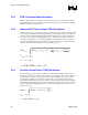
2.3.4 Resistor Current Sense TOB Calculations
Resistor sensing topologies have the capability to provide the tightest TOB solutions due to a
wide industry selection of precision resistors. However, the accuracy comes at a price. Resistors
are placed in series with the output current, which results in substantial power loss and heat
generation. The resulting power dissipation requires large, expensive, high wattage resistors,
which demand additional cooling to keep components and motherboard layers below maximum
allowable temperature limits. Power loss may be mitigated by selecting a low value of resistance,
however minimum signal amplitude must be considered for adequate current conversion (i.e.,
signal to noise ratio).
)
n
k
k.(V)k.VID(TOB
rsense
rsense
gmAVPVIDmanuf
2
222
++=
AVPmaxAVP
R.IV =
ripplemanuf
VTOBTOB +=−+ /
)
n
kk
.(V)
n
k
k.(V)k.VID(TOB
ph
CL
AVPdyn
ph
ESR
gmAVPVIDmanuf
22
2
2
222
+
+++=
AVPdynAVPdyn
R.IV =
AVPmaxAVP
R.IV =
TCripplemanuf
VVTOBTOB
+
+
=−+ /