
Voltage Regulator-Down (VRD) 10.1 Design Guide

Processor Vcc Requirements
R
30 Design Guide
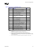
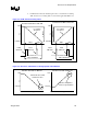
Table 2-8. D-VID Validation Summary Table
Parameter Minimum Typical Maximum
VID 0.8375 V - 1.6000 V
Voltage Transition 0.7575 V 0.762 5V 0.7675 V
Transition Time - - 350 µs
1
Current Load 5 A - VR TDC
NOTES:
1. Time is measured from 0.4 V on rising edge of the first D-VID code to the convergent Vcc voltage
value after the final D-VID code is transmitted
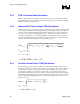
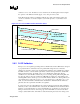
2.7 Processor Vcc Overshoot (REQUIRED)
2.7.1 Specification Overview
Intel desktop processors in VRD10.1 systems are capable of tolerating short transient overshoot
events above VID on the Vcc supply that will not impact processor lifespan or reliability.
Maximum processor Vcc overshoot, V
OS
, cannot exceed VID+V
OS
-
MAX.
Overshoot duration,
T
OS
, cannot stay above VID for a time more than T
OS
-
MAX.
See
Table 2-9
and
Table 2-10
for
details.
Table 2-9. Vcc Overshoot Terminology
Parameter Definition
VOS Measured peak overshoot voltage
V
OS
-
MAX
Maximum specified overshoot voltage allowed above VID
T
OS
Measured overshoot time duration
T
OS
-
MAX
Maximum specified overshoot time duration above VID
Vzc Zero current voltage: The voltage where the measured load line intercepts the voltage axis
Vzco Zero current offset from VID: Vzco = VID – Vzc
Table 2-10. Vcc Overshoot Specifications
Parameter Specification
VOS_MAX 50 mV
TOS_MAX 25 µs
VOS Maximum = VID + VOS_MAX
TOS Maximum = TOS_MAX