
Voltage Regulator-Down (VRD) 10.1 Design Guide


Processor Vcc Requirements
R
Design Guide
35
2.8.2 High Frequency Decoupling
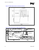
The output filter includes high frequency decoupling to ensure ripple and package noise is
suppressed to specified levels. Ripple limits are defined in section 2.3 and package noise limits
are defined in appropriate processor datasheets in the form of a processor die load line.
High frequency noise and ripple suppression are best minimized by 10
µF, 22 µF or 47 µF multi-
layer ceramic capacitors (MLCC’s). It is recommended to maximize the MLCC count in the
socket cavity to help suppress transients induced by processor packaging hardware. Remaining
MLCC’s should be first placed adjacent to the socket edge in the region between the socket cavity
and the voltage regulator.
Intel recommends a high frequency filter consisting of MLCC’s distributed uniformly through the
socket cavity region with an equivalent ESR of 0.16 m
Ω and total capacitance of 180 µF. The
cavity-capacitor ESL value is not a sensitive parameter, but Intel recommends minimizing the
value to suppress noise. The parallel equivalent ESL on Intel reference boards is equivalent to
0.06 nH. To ensure functionality with all Intel processors, adoption of the reference solution
(defined in the appropriate Platform Design Guidelines) accompanied by full processor load line
validation is strongly recommended.
§