
Voltage Regulator-Down (VRD) 10.1 Design Guide

Output Indicators
R
Design Guide
55
recommended part number is MBT3904Dual, which is provided by several vendors. Transistors C
and D are also contained in a single, 6-pin SOT363 package; recommended part numbers are
PUMZ1 (Philips Semiconductor*), MBT3964DW1(ON Semiconductor*) or equivalent.
9.4 PROCHOT# and VRD Thermal Monitoring
(EXPECTED)
This section describes how to protect the voltage regulator design from heat damage while
supporting thermal design current (VR TDC). Intel does not recommend integrating thermal
sensor features into Vcc PWM controller designs.
Each customer is responsible for identifying maximum temperature specifications for all
components in the voltage regulator design and ensuring that these specifications are not violated
while continuously drawing specified VR TDC levels. In the event of a catastrophic thermal
failure, the thermal monitoring circuit is to assert the signal FORCEPR# and PROCHOT#
immediately prior to exceeding maximum motherboard and component thermal ratings to prevent
heat damage. Assertion of this signal will lower processor power consumption and reduce current
draw through the voltage regulator, resulting in lower component temperatures. Assertion of these
signals degrades system performance and must never occur when drawing less than specified
thermal design current.
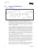
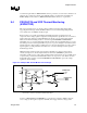
VRD temperature violations can be detected using a thermal sensor and associated control
circuitry (see Figure 9-2). For this implementation, a thermistor (THMSTR) is placed in the
temperature sensitive region of the voltage regulator. The location must be chosen carefully and is
to represent the position where initial thermal violations are expected to occur. When exceeded,
the thermal monitor circuit is to initiate FORCEPR# and PROCHOT# to protect the voltage
regulator from heat damage.
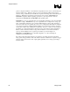
Figure 9-2. Example VRD Thermal Monitor Circuit Design
THMSTR
FORCEPR#
0.1uF
LM393
Vcc(5)
Rtc
6.8k
7.5k
+
-
R3
1k
R2
499
R1
1k
680
Vcc(5)
Q1
130
PROCHOT#
Q2
130
NOTES: Where R
2
= R
1
/R
3
* R
tc
. Thermistor is NTHS0603N02N6801JR or equivalent. Where R
tc
represents
the thermistor resistance at maximum allowable temperature.
Assertion of PROCHOT# and FORCEPR# is governed by the comparator (LM393) using the
sensor voltage (at the negative comparator terminal) and a trigger reference voltage (at the