
Voltage Regulator-Down (VRD) 10.1 Design Guide


Electrical Simulation
R
Design Guide
71
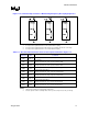
Figure 11-6. Schematic Representation of Bulk and High-Frequency Decoupling Capacitors
NOTES:
1. C1 represents the parallel model for ‘north’ location bulk decoupling
2. C2 represents the parallel model for high frequency decoupling located in the socket cavity
3. C3 represents the parallel model for ‘east’ location bulk decoupling
Table 11-2. Recommended Parameter Values for the Capacitors Models in Figure 11-6
Parameter Value Comments
CMB1 3360 µF
2
Parallel equivalent for ‘north’ capacitors prior to age, thermal, & manufacturing
de
g
radation.
RMB1 1.0 mΩ Parallel equivalent for ‘north’ capacitor maximum ESR.
LMB1 550 pH
1, 2
Parallel equivalent for ‘north’ capacitor maximum ESL.
CMB2 180 µF
2
Parallel equivalent for ‘cavity’ capacitors prior to age, thermal, &
manufacturin
g
de
g
radation.
RMB2 0.16 mΩ
2
Parallel equivalent for ‘cavity’ capacitor maximum ESR.
LMB2 60 pH
1, 2
Parallel equivalent for ‘cavity’ capacitor maximum ESL.
CMB3 2240 µF
2
Parallel equivalent for ‘east’ capacitors prior to age, thermal, and
manufacturin
g
de
g
radation.
RMB3 1.5 mΩ
2
Parallel equivalent for ‘east’ capacitor maximum ESR.
LMB3 712 pH
1, 2
Parallel equivalent for ‘east’ capacitor maximum ESL.
NOTES: :
1. Higher values of ESL may satisfy design requirements.
2. Contact capacitor vendors to identify values for the specific components used in your design