
Voltage Regulator-Down (VRD) 10.1 Design Guide


Electrical Simulation
R
72 Design Guide
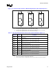
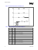
Figure 11-7. Schematic Representation of the LGA775 Socket
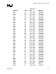
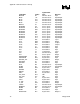
Table 11-3. Electrical Parameters for the Schematic of Figure 11-7
Parameter Value Comments
RSKT1 0.38 mΩ LGA775 ‘north’ segment resistance
RSKT2 1.13 mΩ LGA775 ‘center’ segment resistance
RSKT3 0.29 mΩ LGA775 ‘east’ segment resistance
RVTT1 0.42 mΩ Resistance of VTT Tool load board
RVTT2 0.91 mΩ Resistance of VTT Tool socket adapter (interposer)
RS 100 kΩ VTT Tool current source resistance
LSKT1 40 pH LGA775 ‘north’ segment inductance
LSKT2 120pH LGA775 ‘center’ segment inductance
LSKT3 30 pH LGA775 ‘east’ segment inductance
LVTT1 240 pH Inductance of VTT Tool load board
LVTT2 42 pH Inductance of VTT Tool socket adapter (interposer)