
VRM 9.0 DC-DC Converter Design Guidelines
VRM 9.0 DC-DC Converter Design Guidelines
11
Minimum Vtrip should be the nominal (maximum) Vout
VRM
specified in Table 1
plus 55mV to compensate for remote sense
plus margin to prevent false trips.
Maximum Vtrip should be the maximum, non-operating voltage, V
MAX
, specified in Table 1.
No combination of input voltage sequences should falsely trigger an OVP event.
1.9.2 Fuse Protection for Power Input PROPOSED
The power input (12V) should be protected with a fuse rated not greater than 30A, which sustains
all operating and inrush conditions and which “blows” only on catastrophic failure of the
converter.
1.9.3 Overload Protection EXPECTED
The VRM should be capable of withstanding a continuous, abnormally low resistance on the
output without damage or over-stress to the unit. Output current under this condition will be
limited to no more than 150% of the maximum rated output of the VRM. Latching off or hiccup
mode is acceptable during over-current conditions. The VRM should be capable of starting into
a constant current load of 50% of maximum rated load current with maximum load capacitance,
as defined in Section 1.1.6, without tripping the OCP circuitry. For multiple-processor systems,
errors in current sharing (see Section 1.1.7) during startup should not cause OCP circuits to shut
down the converter.
1.9.4 Reset After Shutdown PROPOSED
If the VRM goes into a shutdown state due to a fault condition on its output (not an internal
failure) it should return to normal operation after the fault has been removed, or after the fault
has been removed and power has been cycled off and on.
2 Module Layout Guidelines
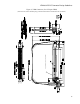
2.1 VRM Connector EXPECTED
The VRM interface with the system board is a 0.100” pitch, 62-pin edge connector, with an
overall 3.95” length: Tyco* 1364125-1 or equivalent. The connector uses a retention clip to hold
the VRM in place. The connector contacts have a maximum rated temperature of 90°C, based on
4-oz. copper lands on the VRM PCB and 19 pin pairs carrying 3.6A each. (Intel does not endorse
the third party products featured and/or mentioned in this document.)
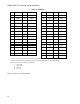
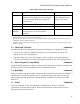
Table 3 shows the VRM pin-out definitions.