
VRM 9.0 DC-DC Converter Design Guidelines

VRM 9.0 DC-DC Converter Design Guidelines
15
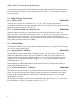
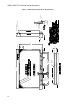
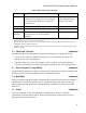
2.2 Mechanical Dimensions PROPOSED
The maximum outline dimensions of the VRM should be as shown in Figure 3:
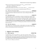
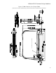
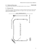
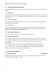
2.3 Retention Clip
The module will require retention hardware to maintain mechanical and electrical contact during
system use and handling. Figure 4 describes one example of such a clip, which fits within the
dimensional envelope of Figure 3.
Figure 4, VRM Retention Clip
(Intel does not endorse the third party products featured and/or mentioned in this document.)
TYCO RETENTION CLIP 1364145-1 OR EQUIVALENT
COIN EDGES ON NOTCH BOTH SIDES BEFORE
FORMING TO REDUCE ABRASION TO CARD 2 PL
USED WITH AMP CONNECTOR 1364125 SERIES
MATERIAL: STAINLESS STEEL UNS S30100
THICKNESS .0250 ± .0005 TEMPER: SPRING.
TYCO RETENTION CLIP 1364145-1 OR EQUIVALENT
COIN EDGES ON NOTCH BOTH SIDES BEFORE
FORMING TO REDUCE ABRASION TO CARD 2 PL
USED WITH AMP CONNECTOR 1364125 SERIES
MATERIAL: STAINLESS STEEL UNS S30100
THICKNESS .0250 ± .0005 TEMPER: SPRING.