
VRM 9.0 DC-DC Converter Design Guidelines


VRM 9.0 DC-DC Converter Design Guidelines
7
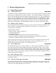
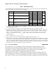
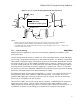
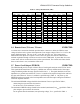
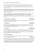
Figure 1, Processor Current during Thermal Monitor Operation
Notes:
⋅
⋅⋅
⋅
Duration of on-off periods depends on processor speed: faster processors have shorter durations.
⋅
⋅⋅
⋅
Other operating system-controlled events could have on-times as short as 700 cycles.
⋅
⋅⋅
⋅
A possible worst-case routine could cause processor Icc to go through a 100% → 40% → 100% set of
transitions within 30-50 cycles.
1.1.7 Current Sharing REQUIRED
Multiple-processor applications require that current-sharing capability be available to avoid
power-plane splits.
Current sharing should be accurate to within 10% of the rated output current over the full output
current range, except during initial power-up and transient responses. For instance, if a particular
VRM model is designed to supply a 50-Ampere processor as a maximum, the difference between
the output currents of two or more VRMs in parallel may be as much as 5 Amperes at any value
of current actually produced, even to the point where one VRM is producing 5 Amperes and one
in parallel with it is producing no current in supplying a 5-Ampere load. There is no time limit
for response to power-up or transients: VRMs must meet all other electrical specifications during
transitions, and output current levels must not damage the VRMs.
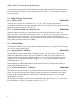
The VRM must supply current equal to (total load) x (1 + tol)/(n + tol), where tol is the current-
sharing accuracy and n is the number of VRMs sharing the load. For example, each of two
parallel VRMs supplying a 130A load could have 66.6A Icc capacity with 5% current sharing
accuracy or 68.1A capacity with 10% accuracy.
One pin of the VRM is reserved for current sharing control for a VRM designed for starpoint or
single-wire current sharing. This pin will be connected to other VRMs within the system.
VRMs designed for current sharing by means of accurate output control need not use this pin. If
a VRM does not use the current sharing pin, it should not be connected on the module.
100%
40%
50%
5%
1
2
1
400
100%
40%
50%
5%
1
5-10
250
20
100% I
max
2.1 -
2.6 µs
2.2 -
2.7 µs
5% I
max
Units
• % of Icc-max
• number of clock cycles