
VRM 9.0 DC-DC Converter Design Guidelines

VRM 9.0 DC-DC Converter Design Guidelines
8
Current sharing among different VRM models, including VRMs from different manufacturers, is
an expected feature, required for most multiple-processor systems. Hot-swapping capability is
not a requirement.
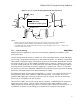
1.2 Input Voltage and Current
1.2.1 Input Voltages EXPECTED
The main power source for the VRM is 12V +5%, -8%. This voltage is supplied by a
conventional computer power supply through a cable to the system board. The system board will
supply local bulk bypassing on the 12V rail.
1.2.2 Load Transient Effects on Input Current EXPECTED
When the VRM is providing an output current step to the load from Iout
MIN
to Iout
MAX
or
Iout
MAX
to Iout
MIN
at the slew rate listed in Section 1.1.1, the slew rate of the input current to the
VRM should not exceed 1.0A/µsec. The system board needs sufficient bulk decoupling to
ensure that the supply voltage on the system board does not go outside of regulation requirements
during times of transient load on the VRM(s).
1.3 Control Inputs
Control inputs should accept an open-collector, open-drain, open-switch-to-ground, low-voltage
TTL or low-voltage CMOS signal.
1.3.1 Output Enable—(OUTEN) EXPECTED
The VRM must accept an input signal to enable the output. An open-circuit or active high
enables the VRM and a ground or active low disables the VRM. The input should have an
internal pull-up resistor between 1kΩ and 10kΩ to 3.3 or 5.0 volts. The maximum low-input
voltage is 0.8V; the minimum high-input voltage is 1.7V. These inputs should be capable of
withstanding up to 5.5V.
When disabled, the VRM should sink less than 100mA from the 12V Input and less than 1A
from shared VRMs that remain on.
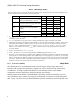
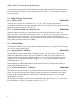
1.3.2 Voltage Identification—(VID[0:4]) REQUIRED
The VRM must accept five lines to set the nominal (maximum) voltage as defined by the table
below. Five processor package pins will have a high-low pattern corresponding to the voltage
required by the individual processor. When all five VID inputs are high (11111), the VRM
should disable its output.
The maximum low-input voltage is 0.8V; the minimum high-input voltage is 1.7V. Each VID
input should have a 1 kΩ ± 10% pull-up resistor to 3.3V ± 5%.