
Laptop User Manual

Intel® PXA26x Processor Family Developer’s Manual 5-15
Direct Memory Access Controller
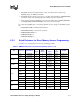
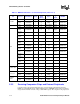
DREQ[1:0]. The DREQ signal can be mapped to one of the 16 available channels. The DREQ
signals are sampled on every peripheral clock (PCLK) and if any of the DREQ signals are sampled
non-zero, a lookup is performed on the corresponding bits in the DRCMRx. This allows requests to
one of the channels to be mapped. If the external peripheral address is in the DSADR, the
DCMDx[FLOWSRC] bit must be set to a 1. If the external peripheral address is in the DTADR, the
DCMDx[FLOWTRG] bit must be set to a 1. This allows the processor to wait for the request
before it initiates the transfer.
If DCMDx[IRQEN] is set to a 1, a DMA interrupt can be requested at the end of the last cycle
associated with the byte that caused DCMDx[LENGTH] to decrease from a 1 to a 0.
5.2.3.1 Using Flow-Through DMA Read Cycles to Service External
Peripherals
A flow-through DMA read for an external peripheral begins when the external peripheral sends a
request, via the DREQ[1:0] bus, to a DMAC channel that is running and configured for a flow-
through read. DCMDx[SIZE] specifies the number of bytes to be transferred. When the request is
the highest priority request, the follow process begins.
1. The DMAC sends a request to the memory controller to read the number of bytes addressed by
DSADRx[31:0] into a 32-byte staging buffer in the DMAC.
2. The DMAC transfers the data in the buffer to the external device addressed in DTADRx[31:0].
3. At the end of the transfer, DSADRx is increased by the smaller value of DCMDx[LENGTH]
and DCMD[SIZE]. DCMDx[LENGTH] is decreased by the same value.
Note: The process shown for a flow-through DMA read to an external peripheral indicates that the
external address increases. Some external peripherals, such as FIFOs, do not require an increment
in the external address.
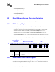
For a flow-through DMA read to an external peripheral, use the following settings for the DMAC
register bits:
• DSADR[SRCADDR] = external memory address
• DTADR[TRGADDR] = companion chip’s address
• DCMD[INCSRCADDR] = 1
• DCMD[INCTRGADDR] = 0
• DCMD[FLOWSRC] = 0
• DCMD[FLOWTRG] = 1
5.2.3.2 Using Flow-Through DMA Write Cycles to Service External
Peripherals
A flow-through DMA write to an external peripheral begins when the external peripheral sends a
request, via the DREQ bus, to a DMAC channel that is running and configured for a flow-through
write. DCMDx[SIZE] specifies the number of bytes to be transferred. When the request is the
highest priority request, the following process begins:
1. The DMAC transfers the required number of bytes from the I/O device addressed by
DSADRx[31:0] to the DMAC write buffer.
2. The DMAC transfers the data to the memory controller via the internal bus.